background image


|

     6

KeyRig 25 User Guide

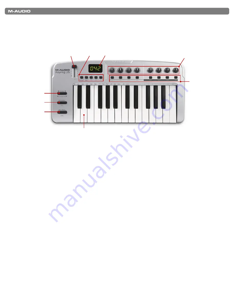
Controls and Connectors

Top Panel


1.

   Keyboard 

– KeyRig 25 has a two-octave, velocity sensitive keyboard. This controller features special “half-action” keys which allow 

KeyRig 25 to be thinner and more portable than traditional controller keyboards.

2.

   Pitch Bend 

– This control lets you create expressive changes in your performances by raising and lowering pitch. Pressing the 

right side of the Pitch Bend control will raise an instrument’s pitch whereas pressing the left side will lower the pitch. Once the Pitch 
Bend control is released, your instrument’s pitch will return to normal.  


 Note that the upper and lower pitch bend limit is determined by settings on your hardware or software synthesizer, not by the Pitch 
Bend control on the KeyRig 25 keyboard. Typically, this can be either a half note or an octave up/down. 

3.

   Modulation 

– This control is used to add expressivity to your performance by changing the intensity of certain effects. By default, 

most synthesizers assign this control to manipulate vibrato (change in intonation) or tremolo (change in volume) although it is usually 
possible to reassign the function of modulation through the instrument’s control panel. 


 The MIDI data range of the Modulation control is 0 to 127, with 0 being the note-unchanged position. Like the Pitch Bend wheel, 
the amount of actual modulation that takes place depends on your instrument’s settings.

4.

   Octave Up/Down 

– The Octave Up/Down control “shifts” the keyboard’s octave range in order to let you play higher or lower 

notes. Press the “” button to shift the keyboard up one octave; press the “Octave -” button to shift the keyboard down one 
octave.  Note that it is possible to shift several octaves in each direction by pressing the “” or “Octave -” buttons more than 
once.

5.

   Assignable Slider 

– This slider sends out MIDI Continuous Controller (CC) data, giving you real-time control over your MIDI 

hardware or software instruments.

6.

   Function Buttons 

– These buttons are used to access all of the various functions and features of the keyboard.  They are 

described in the “Using KeyRig 25” section of this guide

7.

  LED Display 

– The LED screen displays MIDI functions and data selections.

8.

   MIDI Controller Knobs (C1 – C8)

 – These eight MIDI Controller knobs give you real-time control over your MIDI hardware and 

software through MIDI Continuous Controller (CC) messages.

9.

   MIDI Controller Buttons (B1 – B8)

 – Like the MIDI Controller knobs described above, these eight MIDI Controller buttons give 

you real-time control over your MIDI hardware and software through MIDI Continuous Controller (CC) messages.

Summary of Contents for KEYRIG 25

Page 1: ...KeyRigTM 25 User Guide Easy to Use 25 Note USB Keyboard...

Page 2: ...de Overview 12 Assigning MIDI CCs 12 Assigning MIDI Channels 13 Limiting the Range of the Controls 13 Using Controls to Increment or Decrement Values 14 Setting Toggle Values for the Buttons 14 Assign...

Page 3: ...ou get the most out of your new purchase Since this keyboard can be used with many third party music programs you may also wish to review your software s documentation to learn how KeyRig 25 can be us...

Page 4: ...s for any third party software you plan to use with your KeyRig 25 keyboard as they may be greater than the above speci cations Check www m audio com for Windows Vista driver availability Key Rig Virt...

Page 5: ...pport Drivers page at www m audio com This ensures that you have the newest drivers available If you do not have Internet access insert the KeyRig 25 CD ROM into your computer to install the drivers t...

Page 6: ...MIDI data range of the Modulation control is 0 to 127 with 0 being the note unchanged position Like the Pitch Bend wheel the amount of actual modulation that takes place depends on your instrument s...

Page 7: ...etely separate MIDI output port to your music software Refer to the Using KeyRig 25 section of this manual to learn how to engage MIDI Out from USB mode 13 USB Connector Connect a USB cable from this...

Page 8: ...ers to Control Your Software The KeyRig 25 keyboard has a number of assignable MIDI controls knobs buttons sliders etc that can be used to control your music software Each assignable control has its o...

Page 9: ...more about LSB and MSB please refer to the MIDI Messages In Depth section of this manual NOTE Bank change messages must be followed by a Program Change message for the bank change to take effect Simp...

Page 10: ...e included this information for power users who want to explore and use the keyboard s in depth features and additional capabilities to their full extent This information is not required reading for m...

Page 11: ...r to the Enigma User Guide to learn more about how to use the software with KeyRig 25 Sending a Snap Shot Snap Shot is a useful function that can be used to synchronize the receiving MIDI device with...

Page 12: ...e Enter key to con rm the entry If you ve changed your mind press the ADVANCED FUNCTION button to exit Program mode without changing any settings Assigning MIDI CCs To edit a MIDI CC mapping for a but...

Page 13: ...Controls to Increment or Decrement Values Buttons and the pedal can be set to decrement or increment MIDI data values within a de ned range and one by one This is useful if you need precise control o...

Page 14: ...C INC buttons This sets the control for MIDI CC On Off mode 4 Press ENTER to con rm 5 Press the ADVANCED FUNCTION button again followed by the DATA 1 key 6 Enter the number of the MIDI CC you want the...

Page 15: ...ter numbers to allow manufacturers to specify their own controllers Some of the more common messages are now registered by the MIDI Manufacturer s Association and are part of the MIDI speci cation hen...

Page 16: ...e ID for a SysEx message assigned to a controller can be changed using the DEV ID key This key is used for varying the global Device ID of the M Audio KeyRig 25 Assigning the Device ID Press the ADVAN...

Page 17: ...esult is a system of 128 banks that can contain 128 sub banks in each of them which in turn can contain 128 sounds programs within them Bank change messages are useful when calling up sounds from a la...

Page 18: ...Rig 25 keyboard determines the polarity of a sustain pedal when the controller is switched on The sustain pedal is assumed to be in the OFF position i e not pressed when the keyboard is turned on To e...

Page 19: ...Note 0 127 X Number True Voice Velocity Note ON 0 X Note OFF X After Keys X X Touch Ch s 0 Pitch Bend 0 X Control 0 119 0 X Change 120 127 0 X Program 0 127 X Change True Number System Exclusive GM GM...

Page 20: ...e RPN LSB RPN MSB 133 RPN Fine RPN LSB RPN MSB 134 NRPN Coarse NRPN LSB NRPN MSB 135 NRPN Fine NRPN LSB NRPN MSB 136 Master Volume GM Volume LSB Volume MSB 137 Master Pan GM Pan LSB Pan MSB 138 Master...

Page 21: ...40 Chorus Mod Rate GM2 Mod rate 141 Chorus Mod Depth GM2 Mod depth 142 Feedback GM2 Feedback level 143 Send to Reverb GM2 Reverb send level 144 Pitch Bend Pitch shift LSB Pitch shift MSB 145 Program B...

Page 22: ...62 98 0D 13 38 56 63 99 0E 14 39 57 64 100 0F 15 3A 58 65 101 10 16 3B 59 66 102 11 17 3C 60 67 103 12 18 3D 61 68 104 13 19 3E 62 69 105 14 20 3F 63 6A 106 15 21 40 64 6B 107 16 22 41 65 6C 108 17 2...

Page 23: ...String Ensemble 1 49 String Ensemble 2 50 Syn Strings 1 51 Syn Strings 2 52 Choir Aahs 53 Voice Oohs 54 Syn Choir 55 Orchestral Hit 80 Syn Square Wave 81 Syn Sawtooth Wave 82 Syn Calliope 83 Syn Chiff...

Page 24: ...roller 57 58 Controller 58 59 Controller 59 60 Controller 60 61 Controller 61 62 Controller 62 63 Controller 63 64 Sustain Pedal 65 Portamento 66 Sostenuto 67 Soft Pedal 68 Legato Pedal 69 Hold 2 70 S...

Page 25: ...tive change 16 00 7F 00 7F n a 64 0 63 Drum EG Attack Rate relative change 17 00 7F 00 7F n a 64 0 63 Drum EG Decay Rate relative change 18 00 7F 00 7F n a 64 0 63 Drum Instrument Pitch Coarse relativ...

Page 26: ...n the equipment and receiver Connect the equipment to an outlet on a circuit different from that to which the receiver is connected Consult the dealer or an experienced radio TV technician for help AS...

Page 27: ...391 191 Assistance Technique e mail support m audio fr mac m audio fr fax 33 0 1 72 72 90 52 Site Web www m audio fr M Audio Germany Kuhallmand 34 D 74613 Ohringen Germany Technical Support e mail sup...

Reviews: