MM101880V1 R1A
7
4.13 INDICATORS AND DISPLAY MESSAGES
The radio display is made up of 3 lines. Lines 1 and 2 contain eight alphanumeric character blocks and
are used primarily to display system and group names. Line 1 also displays radio status messages. Line 3
is used primarily to display radio status icons. All three lines are used to display menu options when in
the menu mode. If configured, the display backlighting will illuminate upon power up or when radio
controls are operated.
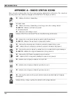
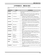
See Appendix A, B, and C for additional details of the specific Jaguar 700P indicators, display messages,
and error messages.
5. CONTROL
FUNCTIONS
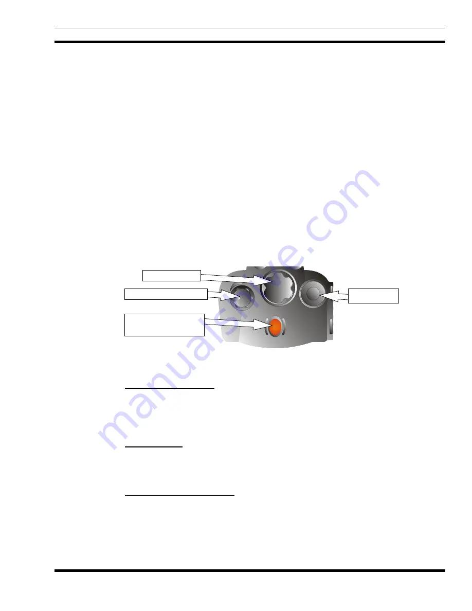
The portable features two rotary control knobs and an emergency button mounted on the top fo the radio.
Push-to-talk, option, and clear/monitor buttons are mounted on the side. The front-mounted keypad has 6
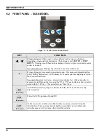
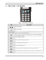
buttons on the Scan model and 15 buttons on the System model.
5.1 TOP
CONTROLS
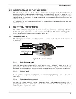
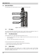
The following describe the three controls located on the top portion of the radio for both the System and
Scan models.
Emergency/Home
Button
On/Off Volume Knob
Control Knob
Antenna
Figure 1 – Top View of Controls
5.1.1 On/Off/Volume
knob
Turns the radio on and off and adjusts audio listening level. Minimum volume levels may be
programmed into the radio to prevent missed calls due to a low volume setting. The volume range is from
a minimum programmed level of zero (shown as OFF in the display) up to 31 which is the loudest level.
5.1.2 Control
knob
Selects systems or groups/channels (depending upon initialization programming). This is a 16-position
rotary knob.
5.1.3 Emergency/Home
button
The Emergency/Home Button is used to automatically select a pre-programmed Group/System by
pressing and holding for a programmed duration. It can also be used to declare an emergency by pressing
and holding for a programmed duration.


