


Page 27 of 51
(North America Edition)
©2019 Lytx, Inc. - Confidential & Proprietary.
This connection is usually made via ring terminal to ground lug in the vehicle, supplied by the
vehicle manufacturer for aftermarket products. If one is not available, ensure that the
connection is solid to a metal portion of the vehicle which is directly grounded to the vehicle
frame. Ensure there is no corrosion or paint interfering with this connection.
Instructions for Basic Connections
1. Find a suitable location to make electrical connections (usually behind/under the dash-
board or power distribution center).
2. Connect the red, brown, and black wires from the Vehicle Interface Cable/Non-ECM,
Device Power Only Cable leads to the vehicle as shown in the
. Be sure to follow the parameters for each wire,
detailed above.
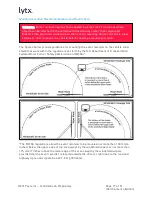
Connect to the Vehicle J1939 Network
You may connect to the vehicle J1939 network with the CAN Coupler, a coupling device. This
device uses inductive technology to allow the event recorder to read the data on the J1939
network without any puncture, cut, or splice into the vehicle cabling.
Refer to the
"Electrical Connection Overview Diagram" on page 21
for the following steps.
1. Connect the CAN Coupler to the Device Power Cable.
2. Find a suitable location along the vehicle J1939 network backbone to insert the CAN
Coupler. The CAN Coupler MUST be installed in the vehicle cab. It cannot be exposed to
moisture or inclement weather conditions.
3. Untwist approximately 2 inches (5 cm) of the vehicle’s J1939 wires, which are always a
green and yellow twisted pair.


