


Lynx NGT-9000s
Installation Manual
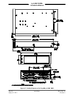
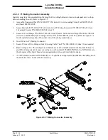
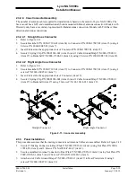
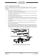
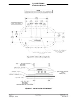
2.3.2.2 P1 Mating Connector Assembly
Installer must take into consideration the length of the wiring harness to insure an adequate service loop
before installing the unit. Refer to Figure 2-5.
1.
Assemble Connector Pins P/N M39029/57-354 (item 11) to wires using Crimp Tool M22520/5-01
and Insert M22520/5-05.
2.
Secure Backshell P/N 9010-17012-01 (item 9) to P1 Mating Connector P/N 9080-17006-01 (item
14) using 4 Screws P/N 2000-10085-01 (item 7).
3.
Secure 2 Wire Clamps P/N 9000-17076-01 (item 10) and 1 Cable Ground Strap P/N 9020-17002-01
(item 27) to Backshell (item 9) using 6 Screws P/N 2000-10087-01 (item 22). (Refer to Figure 2-12
for the installation location of the other side of the cable ground strap.)
4.
Insert Wires to P1 Mating Connector.
5.
Secure Wires to Wire Clamps (item 10) using Cable Ties P/N 1040-10002-01 (item 26) as required.
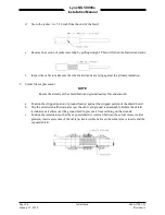
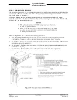
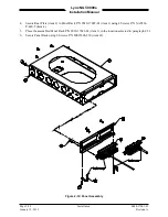
6.
Refer to Figure 2-6. The Configuration Module needs to be installed outside the Backshell (item 9)
and Wire Clamp (item 10) and covered by an overbraid (AA59569R36TXXXX, the XXXX refers to
the diameter of the braid. Secure the exposed sides of the overbraid with tie wraps.
7.
A 9 Pin Sub-D Connector P/N M24308/2-1 or equivalent is required for installations intending to use
the WiFi interface. Connect WiFi Accessory
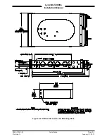
Figure 2-5: P1 Mating Connector Assembly
Page 2-14
Installation
0040-17001-01
January 15, 2015
Revision A


