1
2
Power Supply
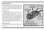
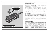
One or two headsets can be connected to the interface using the
locking connector sockets built in to the unit (fig 1). To simplify
operation, the interface draws its power directly from the self contained
Micro System Headset and does not require a separate battery. The
interface is switched on automatically, and is ready for use, once a
headset is connected. Some specialist Lynx headsets do not contain
an internal battery and can not be used with this interface unit.
Push-To-Transmit
In order to provide the greatest flexibility of operation the interface
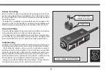
unit is fitted with a built-in 'Push-To-Transmit' (P.T.T.) switch, and a
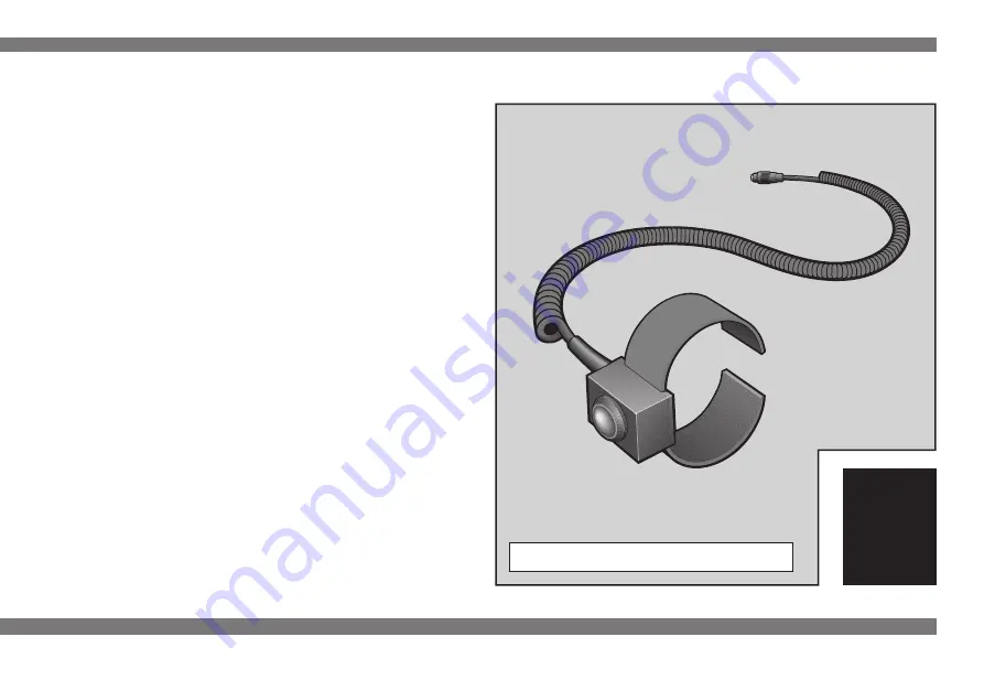
P.T.T. input socket to allow a separate external switch to be connected.
During the operation of a P.T.T. switch, one of the headset
microphones is opened, for radio transmission, and the microphone
of any additional headset is muted. In order to prevent unwanted
noise affecting the radio transmission only one headset is able to
transmit at a time.
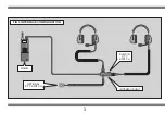
The two headset connection sockets, on the interface unit, are
marked 'Pilot 1' and 'Pilot 2' in relation to the two P.T.T. switches. The
built-in switch controls radio transmissions from a headset connected
to the 'Pilot 1' socket. An external switch controls radio transmissions
from a headset connected to the 'Pilot 2' socket.
A single headset can be used to transmit with either the built-in
switch or an external switch by selecting the appropriate headset
socket. Two headsets can be used with an external switch to allow
both headsets to transmit alternately.
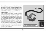
FIG 2 OPTIONAL P.T.T. SWITCH

