background image

Installation

 and Configuration 


Version 1.41, June 2017 


Page 37 of 69 


5.1.4.5


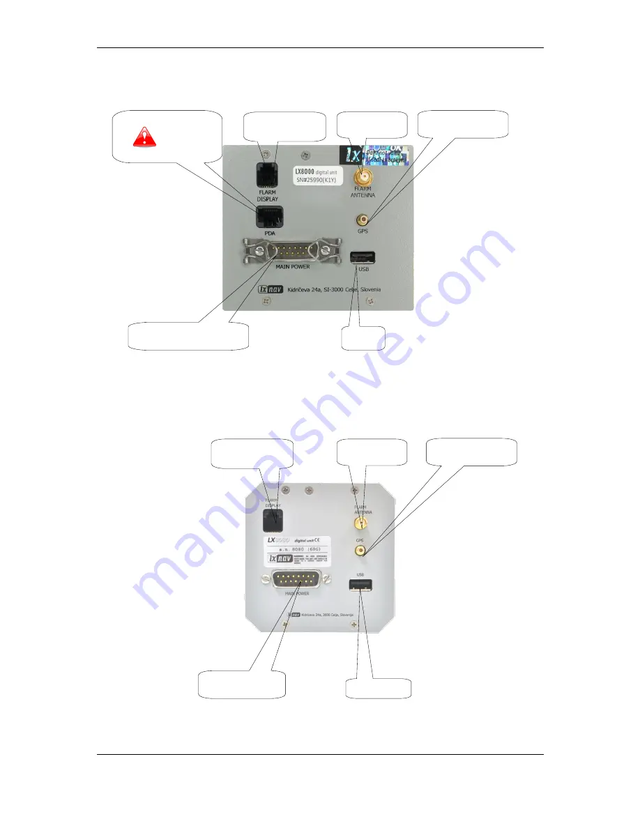
LX8000 Digital Unit Version 2 


5.1.4.6


LX8080 Digital Unit 


GPS antenna 

Flarm HF 

antenna 

PDA port 

   Read manual 


Flarm external 

indicators, splitters 

… 

USB 

device 

Main power supply  

(DU wiring) 

GPS antenna 

Flarm HF 

antenna 

Flarm external 

indicators, splitters 

… 

USB device 


Main power supply  

(LX8080DU wiring) 

Summary of Contents for LX80xx

Page 1: ...LX80xx and LX90xx System Installation Manual 1 41 LXNAV d o o Kidričeva 24a 3000 Celje Slovenia tel 386 592 33 400 fax 386 599 33 522 info lxnav com www lxnav com ...

Page 2: ... 3 5 16 MOP Sensor for jet engines 12 3 5 17 MOP Sensor for Electric Propulsion Gliders 12 3 5 18 Bridges 12 3 6 Cooling Requirements 12 3 7 Mounting Requirements 12 4 Overview of the System 13 4 1 Overview 13 4 2 Communication BUS 13 4 3 Harness and Cables 13 4 4 Splitters 14 4 5 Ethernet Port 14 4 6 Available Cables and Harnesses 14 4 7 Examples of Systems 16 5 Installation and Configuration 19 ...

Page 3: ...y Check of All Peripheral Units 42 5 2 1 Vario Unit 42 5 2 1 1 Connecting the Vario Unit 42 5 2 1 2 Cut Outs 42 5 2 1 1 Wiring 43 5 2 1 2 Connection to the Bus 45 5 2 1 3 Pneumatics 45 5 2 1 4 Audio 46 5 2 1 5 Inputs 46 5 2 2 Installation of Options 47 5 2 2 1 Remote Sticks 47 5 2 2 2 Flarm 49 5 2 2 3 External Flarm or Power Flarm 49 5 2 2 4 ADSB Receiver 50 5 2 2 5 Additional Indicators 53 5 2 2 ...

Page 4: ...that fail in normal use Such repairs or replacement will be made at no charge to the customer for parts and labour provided that the customer shall be responsible for any transportation cost This warranty does not cover failures due to abuse misuse accident or unauthorised alterations or repairs THE WARRANTIES AND REMEDIES CONTAINED HEREIN ARE EXCLUSIVE AND IN LIEU OF ALL OTHER WARRANTIES EXPRESSE...

Page 5: ...ual can be downloaded from http www lxnav com section downloads manuals This manual will guide you through the installation process of all systems components basic setup and check of the system Before using any part of the system please read and understand the installation and user manuals There are no serviceable parts within the unit hence the unit must be taken to the factory for service Openin...

Page 6: ...ment items can be installed Some items have environmental and location requirements others not 3 1 Power Consumption Some modules obtain power from the main unit These modules do not need a circuit breaker as the main unit takes care of this Other items of equipment that have their own power supply should have specified circuit breakers installed ...

Page 7: ...n unit 270mA at max brightness 3A LX8080D repeater unit 230mA at max brightness 3A LX8000 main unit 300mA at max brightness 3A LX8000F main unit 350mA at max brightness 3A LX8000D repeater unit 250mA at max brightness 3A V5 Vario 150mA no audio V9 Vario 130mA no audio V80 Vario 180mA no audio V8 Vario 150mA no audio Vario indicator 57mm I5 80mA Vario indicator 57mm I8 110mA Vario indicator 80mm I8...

Page 8: ...repeater unit 10V 12V 16V V5 Vario 12V from RS485 V9 Vario 12V from RS485 V80 Vario 12V from RS485 V8 Vario 12V from RS485 Vario indicator 57mm I5 12V from RS485 Vario indicator 57mm I8 12V from RS485 Vario indicator 80mm I80 12V from RS485 Remote stick 12V from RS485 Flap sensor 12V from RS485 Magnetic compass 12V from RS485 Radio bridge 12V from RS485 Transponder bridge 12V from RS485 NMEA bridg...

Page 9: ...repeater unit 98 x 88 x 65 mm 500 g V5 Vario 61 x 61 x 92 mm 300 g V9 Vario 61 x 61 x 92 mm 310 g V80 Vario 81 x 81 x 130 mm 400 g V8 Vario 61 x 61 x 92 mm 305 g Vario indicator 57mm V5 61 x 61 x 42 mm 200 g Vario indicator 57mm V8 61 x 61 x 48 mm 200 g Vario indicator 80mm V80 81 x 81 x 44 mm 270 g Remote stick Approx 150 mm Approx 290 g Flap sensor 52 x 23 x 16 mm Approx 190 g Magnetic compass 5...

Page 10: ... C to 60 C V9 Vario 40 C to 80 C 20 C to 60 C V80 Vario 40 C to 80 C 20 C to 60 C V8 Vario 40 C to 80 C 20 C to 60 C Vario indicator 57mm I5 40 C to 80 C 30 C to 60 C Vario indicator 57mm I8 40 C to 80 C 30 C to 60 C Vario indicator 80mm I80 40 C to 80 C 30 C to 60 C Remote stick 40 C to 80 C 30 C to 60 C Flap sensor 40 C to 80 C 30 C to 60 C Magnetic compass 40 C to 80 C 20 C to 60 C Radio bridge...

Page 11: ...quires 94 mm space behind the panel The V8 vario unit harness needs additional 45 mm space Some space should be taken in account also for the pitot static tubes connection Choose a position so that the display will be viewable If the instrument panel is not vertical additional AHRS alignment is required 3 5 7 V80 Vario Requires 130 mm space behind the panel The V80 vario unit harness needs additio...

Page 12: ...l Cable will take an additional 10 mm of space 3 5 14 Wi Fi Module It is plugged into the USB port of the main unit It will require an additional 62 mm of space behind the panel 3 5 15 Bluetooth Module It is plugged in the PDA port of the main unit not available at all types It will require an additional 55 mm of space behind the panel 3 5 16 MOP Sensor for jet engines It is installed in the engin...

Page 13: ...unication with peripheral devices is via the RS232 serial interface This interface is mostly used to connect 3rd party devices into the LXNAV system external Flarm ADSB radio transponder PDA For each device we have a specially designed cable The RS232 connection should be done through the main wiring of the LX device on rounded 5pin binder connectors 4 3 Harness and Cables The main unit cable has ...

Page 14: ...connectors 4 4 Splitters LXNAV systems can use two types of splitters RS485 splitter second seat flaps compass module Radio Bridge Flarm splitter Flarm indicators The RS485 splitter is described in detail in the previous sections A Flarm splitter is used when we want to connect more than one Flarm display to the Flarm port 4 5 Ethernet Port Almost all devices have an Ethernet port which is current...

Page 15: ...nt panel 5P PC Order Nr lx5pc ca PC communication cable with rounded 5pin connector Used for RS232 communication between PC and main unit It can be used also for Flarm firmware update if update via SD card is not successful Cable LX8000 8080 9000 5P FLARM RJ12 Order Nr lx5flarm ca Serial cable for external Flarm connection between rounded 5pin connector and standard Flarm RJ12 plug including power...

Page 16: ...nstallation DS CA RS485 MOP RS485 Bridge RS485 4m DU CA VU CA USB connection DB15 Male DB9 Female DB9 Male RS485 splitter RS485 splitter second MOP Vario indicator SECOND SEAT Remote stick 1 Flap sensor LX8 9xxD SECOND SEAT Radio Bridge Remote stick 2 LX90xx Vario VU CA DU CA Vario LX8 9xx MAIN UNIT Power POWER WI FI ...

Page 17: ...Overview of the System Version 1 41 June 2017 Page 17 of 69 General Connection Options This function may not work on older types of LX9000D RS485 Bridge ...

Page 18: ...Overview of the System Version 1 41 June 2017 Page 18 of 69 ...

Page 19: ...our main rotary switches on the unit While holding the knobs slacken the screws with a screwdriver Now the knobs can be removed never use force to remove the knobs you could damage the rotary switches Remove the four M6 screws Position the LX8080 in the cut out in the instrument panel Secure the LX8080 with the screws Tighten the knobs and fix the covers 5 1 1 Installation of Options All options e...

Page 20: ...Installation and Configuration Version 1 41 June 2017 Page 20 of 69 Drawing is not to scale ...

Page 21: ...Installation and Configuration Version 1 41 June 2017 Page 21 of 69 5 1 2 2 LX9070 Cut Out Drawing is not to scale ...

Page 22: ...Installation and Configuration Version 1 41 June 2017 Page 22 of 69 5 1 2 3 LX9050 Cut Out Drawing is not to scale 5 1 2 4 LX8080 Cut Out Drawing is not to scale ...

Page 23: ...Installation and Configuration Version 1 41 June 2017 Page 23 of 69 5 1 2 5 LX8000 Cut Out Drawing is not to scale ...

Page 24: ...Installation and Configuration Version 1 41 June 2017 Page 24 of 69 5 1 3 Dimensions 5 1 3 1 LX9000 Dimensions 113 145 18 107 139 37 11 46 08 Flarm port GPS antenna Flarm antenna USB port Main port ...

Page 25: ...Installation and Configuration Version 1 41 June 2017 Page 25 of 69 5 1 3 2 LX9070 Dimensions 113 50 180 70 174 70 107 46 08 37 11 Flarm port GPS antenna Flarm antenna USB port Main port ...

Page 26: ...Installation and Configuration Version 1 41 June 2017 Page 26 of 69 5 1 3 3 LX9050 Dimensions 83 136 130 77 71 05 61 57 Flarm port GPS antenna Flarm antenna USB port Main port PDA port ...

Page 27: ...Installation and Configuration Version 1 41 June 2017 Page 27 of 69 5 1 3 4 LX8080 Dimensions 82 82 63 63 R39 85 68 35 59 61 Flarm antenna GPS antenna USB connector Main port PDA port Flarm port ...

Page 28: ...Installation and Configuration Version 1 41 June 2017 Page 28 of 69 5 1 3 5 LX8000 Dimensions 69 85 61 11 97 93 85 60 81 Flarm antenna GPS antenna USB connector Main port Flarm display ...

Page 29: ...ion and Configuration Version 1 41 June 2017 Page 29 of 69 5 1 3 6 V5 V9 Dimensions 93 51 107 01 61 61 23 58 13 50 15 13 50 52 47 38 47 38 R56 30 Main port Audio port Static pressure Total pressure Total energy ...

Page 30: ...Installation and Configuration Version 1 41 June 2017 Page 30 of 69 5 1 3 7 V8 Dimensions 61 47 38 61 47 38 112 90 99 70 Audio port Total energy Main port Total pressure Static pressure ...

Page 31: ...Installation and Configuration Version 1 41 June 2017 Page 31 of 69 5 1 3 8 V80 Dimensions 80 20 80 90 63 63 131 65 148 52 Audio port Main port Static pressure Total energy Total pressure ...

Page 32: ...Installation and Configuration Version 1 41 June 2017 Page 32 of 69 5 1 3 9 I5 Dimensions 485 connector 485 connector 485 connector ...

Page 33: ...Installation and Configuration Version 1 41 June 2017 Page 33 of 69 5 1 3 10 I8 Dimensions 485 connector 485 connector 485 connector ...

Page 34: ...Installation and Configuration Version 1 41 June 2017 Page 34 of 69 5 1 3 11 I80 Dimensions 485 connector 485 connector 485 connector ...

Page 35: ...5 1 4 2 LX9050 GPS antenna Flarm HF antenna ETHERNET Network connector DO NOT USE IT Flarm external indicators splitters USB memory stick Main power supply LX9000DU wiring Flarm external indicators splitters PDA port GPS antenna USB memory stick Main power supply LX9000DU wiring Flarm HF antenna ...

Page 36: ...00 Digital Unit PDA port GPS input port USB memory stick Main power supply LX9000DU wiring GPS antenna Network connector DO NOT USE IT Flarm HF antenna Flarm external indicators splitters USB memory sticks Connector to USB1 port Colibri or any other IGC Flight recorder Main power supply LX8000DU wiring ...

Page 37: ...Digital Unit Version 2 5 1 4 6 LX8080 Digital Unit GPS antenna Flarm HF antenna PDA port Read manual Flarm external indicators splitters USB device Main power supply DU wiring GPS antenna Flarm HF antenna Flarm external indicators splitters USB device Main power supply LX8080DU wiring ...

Page 38: ... Digital Unit Version 2 5 1 4 8 LX8080 Digital Unit Simple Version GPS antenna Flarm HF antenna Flarm external indicators splitters PDA port Read manual USB device Main power supply LX8080DU wiring GPS port Read manual PDA port Read manual USB device Main power supply LX8080DU wiring ...

Page 39: ...8080 LX8000 1 2 3 4 5 6 6 5 4 3 2 1 Pin numbers Pin Number Description 1 open 2 3 3V DC max 100mA 3 GND 4 Flarm Data Out 5 Flarm Data In 6 Ground 5 1 4 10 Flarm Port on LX9xxx 1 2 3 4 5 6 Pin numbers Pin Number Description 1 output 12V DC to supply GPS 2 output 3 3V DC max 100mA 3 GND 4 Flarm Data Out 5 Flarm Data In 6 Ground ...

Page 40: ...ransmit from LXNAV RS232 e g Computer IPAQ38 39xx 4 input Receive to LXNAV RS232 e g Computer IPAQ38 39xx 5 output Transmit from LXNAV V7 LV TTL 3 3V e g Oudie HP302 HP31x 6 input Receive to LXNAV LV TTL 3 3V e g Oudie HP302 HP31x 7 8 5V OUTPUT maximum 1A The RJ45 plug is NOT designed in accordance with IGC standard It can be used only with a dedicated cable Do not plug unknown cables into it as i...

Page 41: ...on 1 output 12V DC to supply GPS 2 3 N C 4 input Receive to main display unit RS232 e g NANO power 232 5 output Transmit from LXNAV main display unit RS232 e g NANO power 232 6 Ground 5 1 4 13 Colibri Port 6 5 4 3 2 1 Pin numbers Pin Number Description 1 GND 2 RS232 RX input receive to LX8000 3 RS232 TX output transmit from LX8000 4 NC no connection 5 NC no connection 6 12 V output ...

Page 42: ...hould use a minimum of 0 5 mm AWG20 wires When the main unit is connected to the vario and other peripheral units we can carry out a functionality test After power up the vario unit should turn on Other peripheral units have their own visual indication so they will be tested via the main unit 5 2 1 Vario Unit 5 2 1 1 Connecting the Vario Unit The vario unit is connected to the main unit via the RS...

Page 43: ...unit 1 6 2 7 3 8 4 9 5 SUBD15 Connector female LX9000 DIGITAL UNIT 12V DC OUT white red shield black yellow GND 12V B A RS485 OUT SUBD9 female GND LABEL 12V DC IN 1 9 2 10 3 11 4 12 5 13 6 14 7 15 8 Data Out Data In B A 1 2 3 4 5 BINDER 5Pin Male PC RS232C 09 0097 00 05 White Data In Black Data Out Shield GND 1 3 5 30 cm 50cm Red 12V 2 GND GND GND shield shield LABEL RS232 LABEL RS485 ...

Page 44: ...IELD GND SHIELD GND SHIELD GND SHIELD GND SHIELD GND SHIELD 4 zilni tasker RS485 IN SUBD9 male There is also CAN bus connector which is prepared for the future DO NOT CONNECT IT ANYWHERE 5 2 1 1 3 V5 V8 V9 V80 Vario Unit Wiring 1 6 7 4 9 5 SUBD15 Connector female V5 white red shield black yellow GND 12V B A GND SHIELD SC 1 9 2 10 3 11 4 12 5 13 6 14 7 15 8 B A SC switch 30 cm 50 cm VP switch VP 50...

Page 45: ...cm 30 cm 50 cm LABEL AUDIO OUT LX 9000 VARIO UNIT Wiring VP switch V P 50 cm green Brown DS1820 O A T 1 5m O A T LABEL OAT LABEL VARIO PRIORITY LABEL SC LABEL RS485 shield shield shield shield LABEL PC LX LABEL LX9000DS COMPASS LCDVARIO 5 2 1 2 Connection to the Bus The vario is connected to the main instrument via the RS485 bus directly or via a RS485 splitter if there will be more units connecte...

Page 46: ...ected correctly before the first power on The power wires red and blue should be connected to the main display unit It is VERY IMPORTANT to use an external fuse max 3A Power supply cables should use a minimum of 0 5 mm wires 5 2 1 4 Audio The Audio speaker is plugged into the vario unit s Audio port The Audio port has a standard 3 5mm phono jack mono If an old vario is being upgraded the user must...

Page 47: ...ll options Rear Seat Device Remote Control Compass Module secondary vario indicators are prepared for connection to the RS485 system bus by use of RS485 splitting units Installation of any option is plug and play and therefore requires only mechanical installation work The main display unit also powers all devices connected to the bus An automatic fuse built into the main display unit prevents dam...

Page 48: ...trol the repeater unit which is installed on the 2nd seat 5 2 2 1 1 2nd Remote Stick DS The 2nd remote stick is used normally to control the 2nd seat unit The 2nd remote stick has its own RS485 splitter This remote stick is specially marked 2nd remote stick on delivery In case there are two remote sticks in the system it is necessary to connect the RS485 splitter with the main RS485 bus via a spec...

Page 49: ...ned vertically as far as possible away from metal parts cables and instruments On new types of gliders carbon fuselages we have experienced poor Flarm reception This can be avoided by moving the antenna to a more open space We have very good experience installing the Flarm antenna in the tail of the glider 5 2 2 3 External Flarm or Power Flarm If the main display unit has no internal Flarm unit th...

Page 50: ...ce For connection to a Power Flarm a special cable LX5PF is available with a RJ45 connector on the Flarm side 5 2 2 4 ADSB Receiver It is possible to connect an ADSB receiver TRX 1090 from Garrecht Avionics www garrecht com to a system with a built in Flarm unit The TRX 1090 can only be connected to a system with the integrated Flarm option The TRX 1090 has been developed to upgrade the FLARM coll...

Page 51: ...X Tool program you should configure the TRX 1090 to be used together with the system The TRX Tool can be downloaded http www garrecht com under the Support Downloads Software section Run the TRX Tool program and connect the TRX 1090 to PC using a USB cable Select the Port4 tab and change connected equipment to LX8000 or FLARM if no RX line connected Select the Port2 tab and change Baudrate to 1920...

Page 52: ...jects 5 2 2 4 2 Connecting the TRX 1090 to the System Disconnect the cable from the Flarm external display and connect the free cable to Port4 on the TRX 1090 Use the LX9000 TRX cable not included must be ordered separately and connect it between Port2 and the PC port on the main display unit On the main display unit go to the setup menu and choose the Hardware Flarm menu item Change mode to Ext P...

Page 53: ... LX9000 FLARM via cable Flarm TRX1090 TRX Port4 Flarm original or compatible LX9000PC 5pin rounded connector via cable TRX LX9000 TRX Port2 Flarm Compatible display set to 19200 5 2 2 5 Additional Indicators Indicators are connected to the RS485 bus via supplied RS3485 cables and additional RS485 splitters ...

Page 54: ...t part of the package If you don t have a spare port on the RS485 splitter you must order it including the radio bridge cable 5 2 2 7 1 Installation of 485 to 232 Bridge The RS485 splitter requires a small modification before the Bridge can be fitted It is necessary to remove two HEX screws where Bridge will be connected and replace by two spring locks that are in the package Then fixing the Bridg...

Page 55: ...nformation please refer to the Radio Transponder Bridge manual 5 2 2 7 4 Transponder Bridge UPDATED The Transponder Bridge is the same part of hardware as the NMEA Bridge On the main unit it can be configured as a Transponder Bridge which can communicate with the supported Transponders for more information please refer to the Radio Transponder Bridge manual 5 2 2 8 Wi Fi Module The Wi Fi dongle mu...

Page 56: ...nected to the CAN bus DB9 of the FCU On this side 3 wires are needed to be soldered to the right pins 1 6 2 7 3 8 4 9 5 DB9 Female 1 6 2 7 3 8 4 9 5 DB9 Female 1 6 2 7 3 8 4 9 5 DB9 Male FCU CAN Female Female CAN_H CAN_L CAN_H CAN_L GND GND No additional termination resistors needed 1 6 2 7 3 8 4 9 5 DB9 Male FES bridge 1 6 2 7 3 8 4 9 5 DB9 Male 1 6 2 7 3 8 4 9 5 DB9 Female LX9000 RS485 B RS485 A...

Page 57: ...LX9000 RS485 B RS485 A or RS485 Splitter 12V GND RS485 A RS485 B 12V GND 5 2 2 13 FlarmLED Display The FlarmLED display is used to display Flarm warnings It must be installed at a visible location so that pilot can immediately see collision warnings The Flarm LED is connected via a standard Flarm cable with RJ12 6 pin connectors Power is supplied over the 3V pin 5 2 2 13 1 FlarmLED Pinout Pin Numb...

Page 58: ...Installation and Configuration Version 1 41 June 2017 Page 58 of 69 5 2 2 13 2 Cut Out Front view Drawing is not to scale ...

Page 59: ...d at a visible place so that the pilot can see collision warnings immediately FlarmView is connected via a standard Flarm cable with RJ12 6 pin connectors Power is supplied over the 12V pin 5 2 2 14 1 Pinout 1 2 3 4 5 6 Pin numbers Pin Number Description 1 Power input 12VDC On version 2 2 Power input 3 3VDC On version 1 3 GND 4 input Data in RS232 receive line 5 output Data out RS232 transmit line...

Page 60: ...e same display as FlarmView only with a different housing FlarmView57 is connected via standard Flarm cable with RJ12 6 pin connectors Power is supplied over the 12V pin 5 2 2 15 1 Cut Out The FlarmView57 is installed in one standard 57mm cut out If there is none available prepare it according to the picture below Drawing is not to scale ...

Page 61: ... of 69 5 2 2 15 2 FlarmView 57 Pinout 1 2 3 4 5 6 1 2 3 4 5 6 Pin numbers Pin numbers Pin Number Description 1 Power input 12VDC On version 2 2 Power input 3 3VDC On version 1 3 GND 4 input Data in RS232 receive line 5 output Data out RS232 transmit line 6 Ground ...

Page 62: ...ation and Configuration Version 1 41 June 2017 Page 62 of 69 5 2 2 16 Flarm ACL FlarmACL is a box which can switch an Anti Collision light on or off This switching can be automatic or manual 5 2 2 16 1 Wiring ...

Page 63: ...41 June 2017 Page 63 of 69 5 2 2 16 2 LXxxxx TRX1090 FlarmACL FlarmLED LX9000 FLARM Port TRX1090 LED Indicator DB15 Binder Flarm ACL Input Output Output Port 4 Port 3 Port 2 Port 1 12V Power White 12V Black Ground Power GND 12V Power Back side ...

Page 64: ...XxxxxDs PowerFlarm FlarmACL FlarmLED LX9000 FLARM Port LED Indicator DB15 Binder 12V Power White 12V Black Ground Back side Power FLARM Flarm ACL 12V Power Input Output Output Power GND LX9000DS FLARM Port DB15 Back side LED Indicator 12V Power Do not connect external power RJ45 Connector ...

Page 65: ... 5 2 2 16 4 LXxxxx PowerFlarm FlarmACL FlarmLED LX9000 FLARM Port LED Indicator DB15 Binder 12V Power White 12V Black Ground Back side Power FLARM Flarm ACL 12V Power Input Output Output Power GND FLARM Port LED Indicator DS Do not connect external power RJ45 Connector ...

Page 66: ...6 Data Output Input 7 GND 8 GND 5 2 2 17 Bluetooth Module The LXNAV Bluetooth module is a special device which can be used only in combination with a LXNAV PDA port RJ45 Connecting to other similar ports will damage the unit 6 Firmware Update Once the instruments have been installed or an upgrade performed the firmware of the various devices should be updated Refer to the instructions in the User ...

Page 67: ...tic Files A Diagnostic file can be downloaded from the main unit under Setup About If a SD card is in the SD socket the user can copy the diagnostic file to the SD card If a Wi Fi module is plugged in and wireless network is available the user can send this file via email directly to LXNAV ...

Page 68: ... dimensions minor graphical changes May 2016 Corrections to English language text added I5 I8 I80 dimensions radio transponder bridge connections were removed from the manual August 2016 Moved wiring chapter 5 2 1 1 1 September 2016 Added wiring chapter 5 2 2 16 2 5 2 2 16 3 5 2 2 16 4 November 2016 Updated chapter 6 Added Colibri port June 2017 Corrections to English language text ...

Page 69: ...LXNAV d o o Kidričeva 24a 3000 Celje Slovenia tel 386 592 33 400 fax 386 599 33 522 info lxnav com www lxnav com ...

Reviews: