


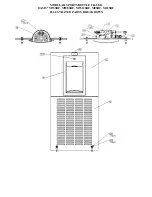


MODULAR SPORTS BOTTLE FILLER
OASIS
®
MWSBF, MW8SBF, MW12SBF, M8SBF, M12SBF
INSTRUCTIONS
1.
INSPECTION
Inspect the cartons and various components for evidence of rough handling and concealed damage. Damage claims should be filed with the
carrier.
2.
INSTALLATION, PLUMBING & ELECTRICAL CONNECTIONS
a)
Note:
The following states require a licensed plumber to install cooler; AR, GA, MA, MI, OK, RI, SC, SD, TX, VT and WI.
CA, KS, MN, NM and OR allow for a state-registered installer or contractor as well. State and local plumbing codes may prohibit the
use of saddle tapping valves for water line connection in some applications. All connections must conform to applicable plumbing codes.
b)
Plumbing rough-in and wall opening should be prepared as shown on roughing-in drawing.
c)
Insert frame assembly into wall opening and secure to studs. NOTE: FRONT FLANGE OF FRAME(S) MUST BE FLUSH WITH THE
FINISHED WALL SURFACE.
d)
Install drain receptor to frame with screws provided.
e)
A 2X4 junction box is provided for the installation of a 115 volt receptacle. The bottle filler is provided with a power cord with a
grounded NEMA 15 plug. It is recommended that flexible conduit be used to supply power to the junction box and chiller if used. Check
the electric current available. Type and voltage must be the same as listed on the unit data plate.
f)
Refer to the appropriate connection diagram for water and drain connections. Check for leaks.
g)
The lower panel can be secured with the provided key locks or screws. The M8SBF features one lockable and one non lockable lower
panel, these are interchangeable.
MODELS WITH CHILLER
h)
Attach cradle mounting angles to unit mounting cradle with 4 screws provided. Slide unit mounting cradle into frame and secure in place
with 4 screws, provided. (Cradle is used only when cooling unit is to be installed.) NOTE: BOTTOM FLANGE ON CRADLE IS TO
BE BEHIND FRAME FRONT FLANGE.
i)
Slide cooling unit onto cradle.
M8SBF & M12SBF WITH FOUNTAIN
j)
Install the fountain mounting plate to the frame assembly using the provided screws.
k)
Place the upper panel in place on the frame top angle and fasten with 2 screws, provided, at the bottom.
l)
Remove the bottom plate from the fountain arm. Save the screws.
m)
Snap the reveal gasket over the back end of the fountain arm.
n)
Add compression connector, furnished by others, to the fountain waste tube and slide back approximately 3" out of the way. Refer to the
appropriate connection diagram.
o)
Hang the fountain on the mounting plate studs. NOTE: AS THE FOUNTAIN IS HUNG, FEED THE WASTE TUBE INTO THE
WASTE STUB ON THE WALL SIDE.
p)
Tighten the fountain to the mounting plate with the 5/16-18 nuts and washers and the 1/4-20 bolts and washers provided.
q)
Slide the reveal gasket(s) back into the notch between the panel and the arm. The gasket serves as an appearance item only (to close up
any opening around the panel and the mounting plate).
3.
OVERLOAD PROTECTION
(systems with chiller)
The compressor motor is equipped with an automatic reset protector which will disconnect the motor from the line in case of overload.
4.
LUBRICATION
(systems with chiller)
This unit is equipped with a hermetically sealed compressor. No additional lubrication is required. The fan motor installed on this unit
seldom needs oiling. If required, a few drops of SAE 10 oil should be used.
5.
TO DISCONTINUE USE OF SYSTEMS WITH CHILLER
Drain cooler when removed from service: (1) Remove grille, (2) Close supply valve, (3) Provide container to catch water, and remove drain
plug,
6
MAINTENANCE
(systems with chiller)
The only maintenance required is the removal of dirt and lint from the condenser. Inspection should be made at 3 month intervals. Remove
the grille and clean the condenser with a vacuum attachment.
WARNING
The warranty and the Underwriters' Laboratory Listing for this machine are automatically voided if this machine is altered, modified, or combined
with any other machine or device. Alteration or modification of this machine may cause serious flooding and/or hazardous electrical shock or fire.
EXCEPT AS SET FORTH HEREIN, THE MANUFACTURER MAKES NO OTHER WARRANTY, GUARANTEE OR AGREEMENT
EXPRESSED, IMPLIED, OR STATUTORY, INCLUDING ANY IMPLIED WARRANTY OR MERCHANTABILITY OR FITNESS FOR A
PARTICULAR PURPOSE.
222 East Campus View Blvd. • Columbus, OH 43235 U.S.A.
1-800-950-3226
www.oasiscoolers.com
is a trademark of Oasis International
© 2009 Oasis International
OASIS
®
is a registered trademark of Oasis International
030099-368 Rev A