background image

4

Names and Functions

16

15 14

13 12 11

10

9

7

8

17

6

5

4

3

2

1

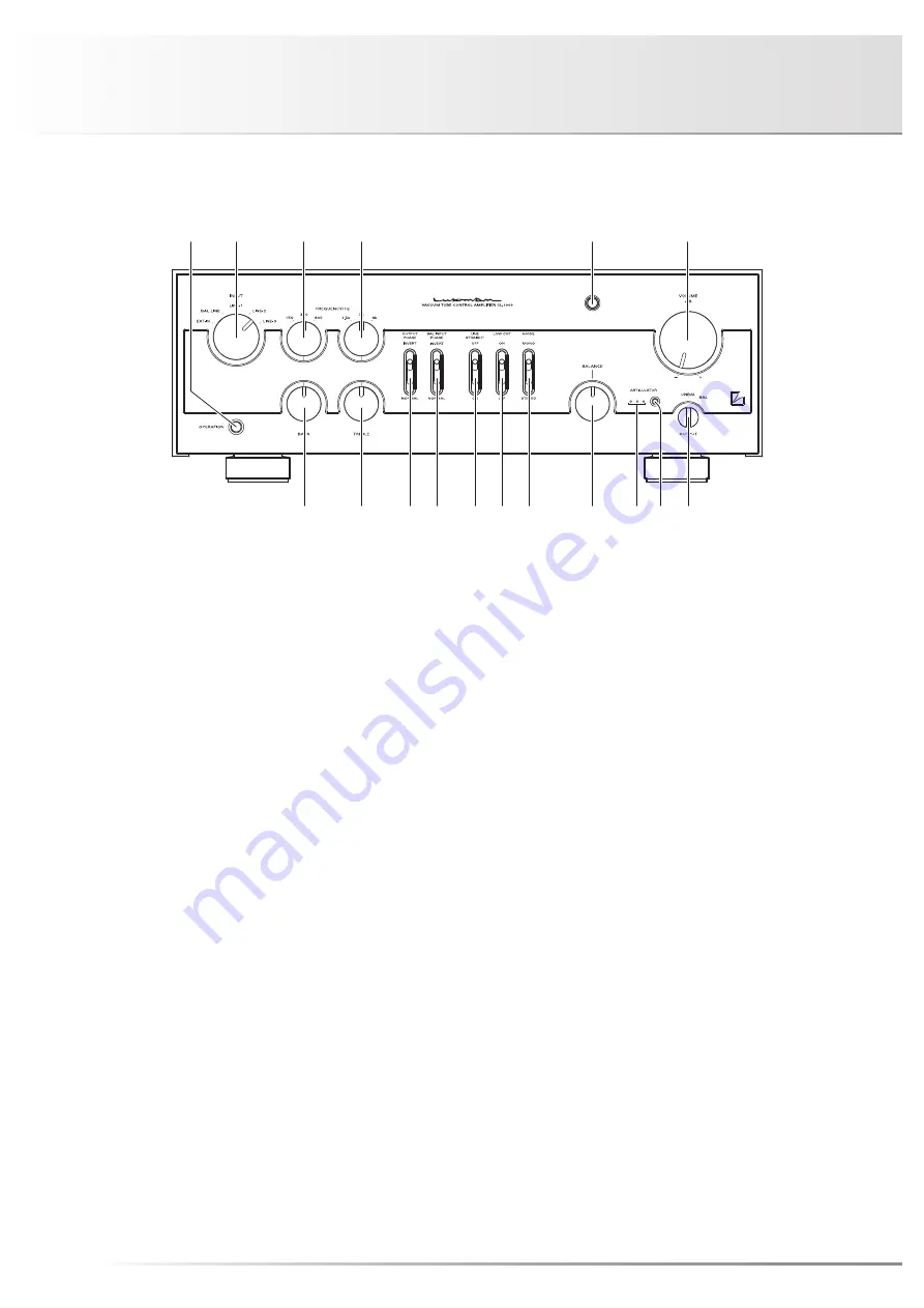
Front panel

1.  Operation switch (OPERATION)

Toggles the power on and off.
When wiring or connection is performed, be sure to turn off 
this switch. When turning on the power switch again after 
turning the unit off, wait for more than one minute.

2.  Input selector (INPUT)

Selects an input device from the devices such as a CD 
player, an SACD player, a tuner, and an analog player 
connected to each input terminal.
This selector has five positions consisting of LINE-1, 
LINE-2, LINE-3, BAL LINE and EXT-IN that correspond to 
each input terminal on the rear panel. To select an input 
source, set the selector to the position of the input source 
to be played back.
The EXT-IN is used for PHONO input.

3.  Low frequency selector switch
 (FREQUENCY/Hz)

Toggles to select frequencies from 150 Hz, 300 Hz, 600 Hz. 
For example, when 150 is selected, the frequencies of 
150 Hz and lower can be adjusted by the tone control for 
bass.

4.  High frequency selector switch
 (FREQUENCY/Hz)

Toggles to select frequencies from 1.5 kHz, 3 kHz, 6 kHz. 
For example, when 1.5 k is selected, the frequencies of 
1.5 kHz and higher can be adjusted by the tone control for 
treble.

5.  Pilot light

This switch turns on and off the power. When connecting 
the input/output terminals, be sure to turn off this switch. 
This light blinks during mute.

6.  Volume control (VOLUME)

Adjusts the sound volume.
There are 34-step changes between ∞ and 0 (–dB).
Sound is not generated when this control is rotated 
counterclockwise to the end. The sound volume gradually 
becomes higher as the control is rotated clockwise.

Summary of Contents for CL-1000

Page 1: ...VACUUM TUBE CONTROL AMPLIFIER CL 1000 Owner sManual...

Page 2: ...Contents Precautions 1 Features of This Unit 2 Names and Functions 4 Connections 9 Operations 12 Block Diagram 13 Specifications 14 Before Asking for Repair Service 16...

Page 3: ...The pin plug to be inserted in each input terminal of this unit shall be pushed in firmly If the grounding terminal is inade quately connected noises including hum may be generated resulting in an adv...

Page 4: ...the input circuit Balance output circuit A dedicated super permalloy transformer is equipped in the output circuit PHASE INVERT function The phase can be switched in accordance with the polarity of th...

Page 5: ...ng structure Every block of the vacuum tube has a floating structure to reduce microphonic noise Cast iron insulator This unit is equipped with gradation cast iron insulators that cuts out unnecessary...

Page 6: ...played back The EXT IN is used for PHONO input 3 Low frequency selector switch FREQUENCY Hz Toggles to select frequencies from 150 Hz 300 Hz 600 Hz For example when 150 is selected the frequencies of...

Page 7: ...sound volume between right and left channels Rotating the control counterclockwise gradually cuts the volume of the right channel rotating the control clockwise gradually cuts the volume of the left c...

Page 8: ...ncy characteristics of the high frequency range When this switch is set in the center position flat frequency characteristics is obtained Rotating the knob clockwise makes the high frequency range enh...

Page 9: ...als INPUTS LINE 1 LINE 2 LINE 3 Coaxial input terminal to receive unbalanced audio signals of a line level Connect these terminals to an unbalanced output of an input device such as a CD player with a...

Page 10: ...als to provide balanced audio signals from this unit Connect these terminals to a balanced input of an output device such as a power amplifier with a balanced cable Audio output signals are selected w...

Page 11: ...function Connect the output of an analog player with phono equal izer embedded to the line input of this unit How to connect the input terminals to input devices such as a CD player Connect between th...

Page 12: ...10 Connections Normal stereophonic playback CD SACD PLAYER L R L R L R L R GND POWER AMP 1 POWER AMP 2 L R L R SPEAKER SYSTEM 1 L R SPEAKER SYSTEM 2 L R D A CONVERTER ANALOG PLAYER...

Page 13: ...UM TUBE CONTROL AMPLIFIER CL 1000 POWER AMP L ch POWER AMP R ch L LOW R LOW L HIGH R HIGH SPEAKER SYSTEM L R CD SACD PLAYER L R L R L R L R GND D A CONVERTER ANALOG PLAYER Bi amplifier stereophonic pl...

Page 14: ...hen the balance adjustment is not required the balance control is set to the center position When the line straight switch LINE STRAIGHT is set to on the right and left sound volumes cannot be changed...

Page 15: ...ELAY TREBLE VOLUME BASS VOLUME TURNOVER RELAY PHASE SELECT RELAY BAL IN FLAT AMP STRAIGHT RELAY PHASE SEL RELAY OUT PUT BAL 1 LINE 2 LINE 1 BAL 2 MUT BAL UNBAL FLAT AMP BAL UNBAL RELAY MUTE RELAY LOW...

Page 16: ...dB 1 V output 20 Hz to 20 kHz load 50 k EXT IN PHONO 0 3 dB 1 V output 20 Hz to 20 kHz load 50 k S N ratio LINE BAL LINE 120 dB IHF A distortion 1 1 kHz load 50 k EXT IN PHONO MM 108 dB IHF A distorti...

Page 17: ...ower cable Owner s Manual This document Terminal protection cap Safety cautions Power supply 230 V 50 Hz Power consumption 52 W Max external dimensions 460 W x 166 H x 454 D mm including 13 5 mm front...

Page 18: ...minimum level Rotate the volume control or attenuator of the power amplifier to adjust the sound volume The input selector is not set to the source to be reproduced Set the input selector to the sour...

Page 19: ......

Page 20: ...LUXMAN CORPORATION AG00987E90A Printed in Japan 1 3 1 Shinyokohama Kouhoku ku Yokohama shi Kanagawa 222 0033 Japan...

Reviews: