


Wallstation circuits are classified as Class 2 circuits
(USA) and PELV circuits (IEC). As Class 2 circuits,
they comply with the requirements of NFPA
®
70,
National Electrical Code
®
(NEC
®
). As PELV circuits,
they comply with the requirements of IEC 60364-4-
41, VDE 0100 Part 410, BS7671:1992, and other
equivalent standards. When installing and wiring to
these wallstations, follow all applicable national and/or
local wiring regulations. External circuits connected to
input, output, RS232, DMX512, and other communi-
cation terminals of wallstations must be supplied from
a listed Class 2 source or comply with the require-
ments for PELV circuits, as applicable in your country.
CAUTION
!
•
Read all instructions carefully before starting instal-
lation.
•
Lutron recommends that wallstations be installed
by a qualified electrician.
•
Do not connect high-voltage power to low-voltage
terminals. Improper wiring can result in personal
injury or damage to the control or to other equip-
ment.
•
Use only a cloth with warm water and mild soap to
clean faceplates (no chemical cleaners).
Wiring Notes
•
Control Link Wiring
— Power: Two #12 AWG (2.5 mm
2
) PELV (Class
2: USA) wires. Connect to terminals 1 and 2.
— Data: Two shielded #18 AWG (1.0 mm
2
)
PELV (Class 2: USA) wires (twisted, shielded
pair). Connect to terminals 3 and 4.
Lutron offers a one-cable, non-plenum, low-
voltage solution (P/N GRX-CBL-46L), and a
one-cable, plenum, low-voltage solution (P/N
GRX-PCBL-46L). Cable is available in 250 ft.
(76 m) and 500 ft. (152 m) spools. Check
availability outside the U.S.
Add (-250) or (-500) to the end of the P/N to
specify the desired spool length.
•
Sensor/Contact Closure Input Connector Wiring
(optional):
— Three #18 AWG (1.0 mm
2
) PELV (Class 2:
USA) wires.
•
Connect the wallstation to the control link inside
the wallstation’s wallbox or in a junction box (pro-
vided by others) located no more than 8 ft. (2.5
m) from control.
•
Control link wiring must
not
be run in the same
raceway as line voltage.
•
Total control link length is
not
to exceed 2000 ft.
(610 m) unless the signal is boosted using a link
booster (P/N MX-RPTR).
•
The drain/shield wire must be maintained through-
out the control link. Do
not
connect the shield to
earth/ground.
•
Refer to the system installation guide and Lutron
job drawings for power cable and data cable
(control link) wiring restrictions and limitations.
•
Control link requires a link terminator (LT-1) at each
end of the control link. Refer to the LT-1 instruction
sheet for location and installation information.
Occupant Copy
Installation Instructions
3
Summary of Contents for seeTouch SO Series
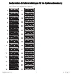
Page 39: ... 50 LED LED 3 4 LT 1 1 2 CCI ...