Page 8
NOTE:
DIP Switch 6 and 7 should be set “ON” if operating with external Control Systems such as Crestron or PANJA (AMX)
The setting of the DIP switches affect the interface control between PRO AV DLC Control Units and your PC or auxiliary A/V equipment. DIP switch options are
described below:
DIP Switch 1: Zone Lock Retain
DIP Switch 2: Scene Lock Retain
DIP Switch 3: Sequence Retain
– In the event of a power outage, the RS232 Interface will retain which PAV6 control units were in ZONE LOCK, SCENE
LOCK and SEQUENCE, respectively. Upon returning power, Control Units that had been in Zone Lock, Scene Lock, or Sequencing will stay locked or
sequencing if the DIP switches are in the ON position, When these DIP switches are in the OFF position, this information will
not
be restored upon power up.
These DIP switches do not affect Zone Lock, Scene Lock, or Sequencing set by a GRX-AV in 4Q mode.
DIP Switch 4: Sequence Type
– Set the scene range that PAV-6M control units will sequence, using the Sequence command. In the OFF position, the
PAV-6 control units will sequence scenes 1 through 4, In the ON position, they will sequence scenes 5 through 16.
DIP Switch 6: Raw Feedback
– In the ON position, the programming interface will report when a button has been pushed or released on a PAV-6 control
unit or low voltage Wallstation. This response varies depending on the type of unit, as listed below:
PRO AV Digital Lighting Controller
(PAV-6M-120 and PAV-6S-120, PAV-6M-230 and PAV-6S-230)
Scene Selection Control
(NTGRX-4S/4S-IR and EGRX-4S/4S-IR)
Architrave Door Jamb Control
(GRX-4S-DW)
Infrared Ceiling Receiver
(GRX-CIR)
A/V Interface Control
(GRX-AV)
Infrared Wireless Remote Controls
(GRX-It & GRX-8IT) The first parameter indicated the address of the Wallstation Control or Control Unit upon which
the button was pushed or released. A capital letter indicates a button was pushed, and a lowercase letter indicates a button was released. The following is a list
of how addresses are indicated.
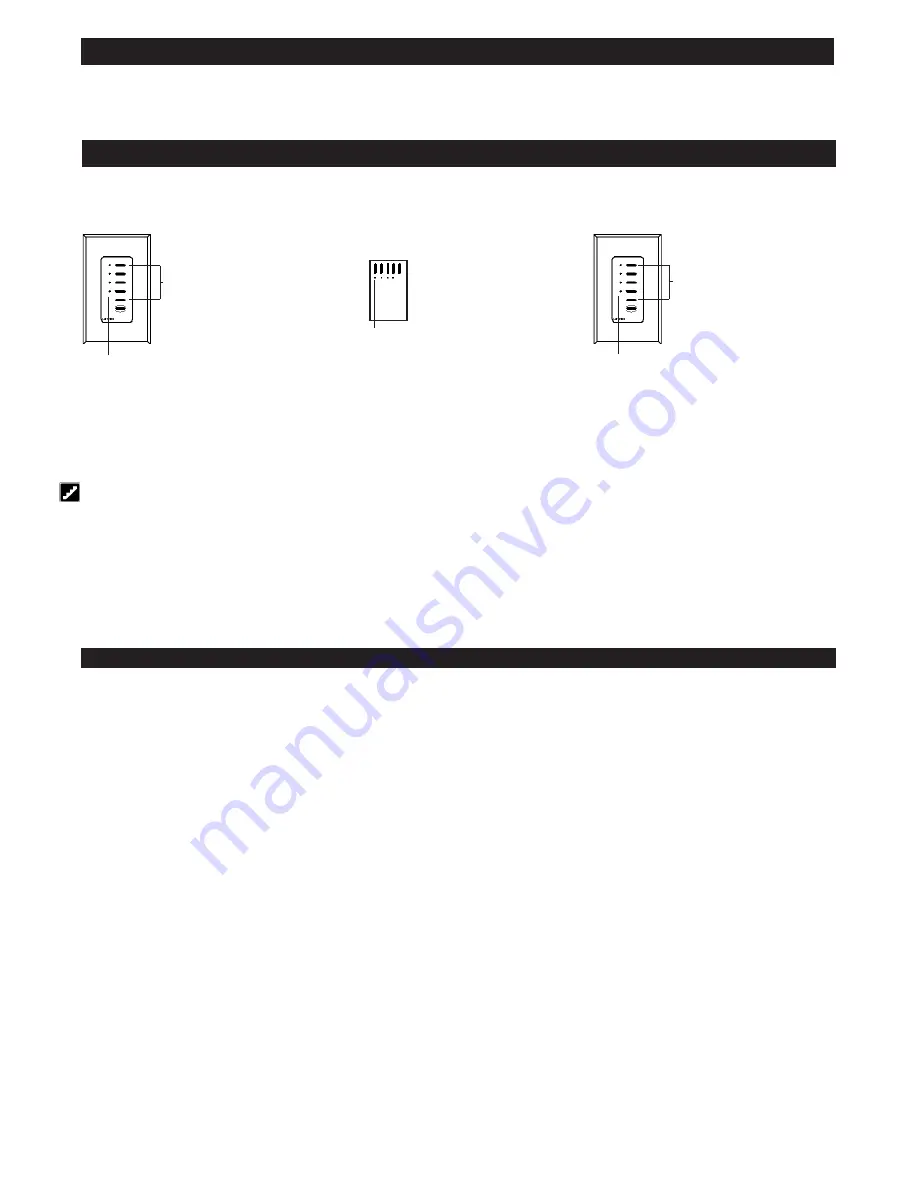
Set up a Wallstation Control to “talk” to a “listening” Control Unit
In order for Wallstation to communicate with a Control Unit, each Wallstation must be individually configured to “talk.”
The communication link is now established. The Control Unit will “listen” when the user presses a button on the Wallstation. You can proceed to the next
Wallstation and set up its communications.
For more specific, step-by-step instructions about setting up communications for each type of PRO AV DLC Wallstation, please refer to the instructions included
with each Wallstation.
3.
Take the Wallstation out of setup mode.
Press and hold top Scene
and OFF button
for 3 seconds . . .
. . . LEDs stop cycling
1.
Enter setup mode.
. . . LEDs cycle—Wallstation is “talking”
Press and hold top Scene
and OFF button for
3 seconds . . .
2.
Make the Control Unit “listen.”
Press and hold LEFT button for 3 seconds
. . . LEDs flash in unison—
Control Unit is “listening”
Identifying the load type for each zone
Lutron ships PRO AV DLC Control Units with all zones set for incandescent/halogen (tungsten) lighting. If your project has non-incandescent loads, change all
non-incandescent zones to the correct load type, through GRX Liaison or AV Control System.
Step 7:
Setting up RS232 Communication
Description
The PAV is equipped with an integral RS232 and capable of programming through Lutron’s Liaison programming software.
This unit allows for up to eight PRO AV units to be interfaced with your personal computer or auxiliary audio/video equipment via RS232. The interface can be
used to execute Control Commands and allow for Status Monitoring. Complete programming is allowed through other RS232 devices. This programming
software includes an internal astronomical timeclock. The GRX-Liaison software can also be used to schedule events, make Sequences, and program additional
PAV6S.
DIP Switches on Interface Board
Summary of Contents for PAV6M-120
Page 15: ...Page 15...


