


51
Index No.
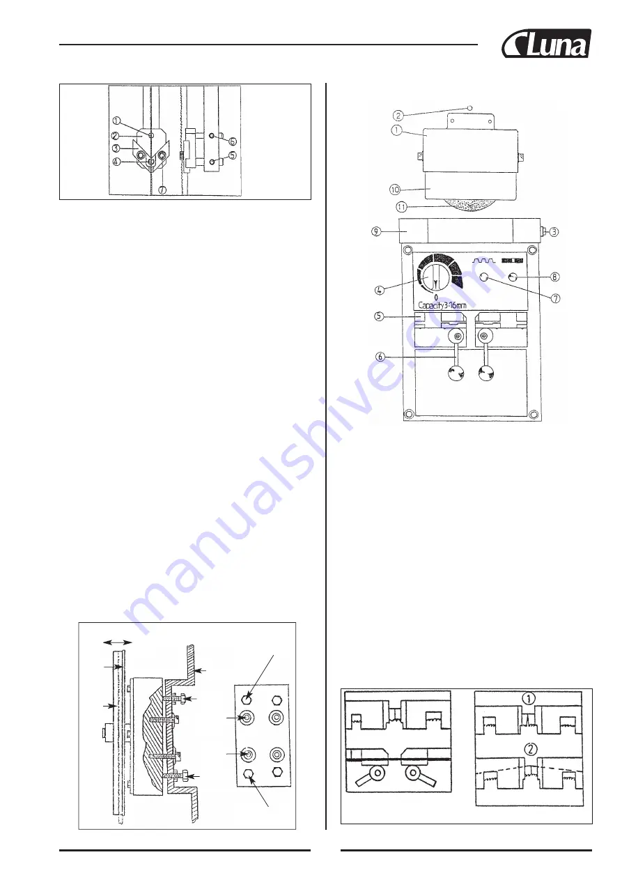
Description
1.
Sandwheel upper cover
2.
Grinder pilot light
3.
Welding light switch
4.
Upset force selector
5.
Blade jaws
6.
Jaw clamping handles
7.
Annealing push button
8.
Welding push button
9.
Lamp shade
10.
Sandwheel shield
(12) Welding blades
Your machine is equipped with a resistance butt welder (see the figure in
front page), with blade shear and grinder. The blade shear is provided for
cutting blade to proper lenght and for cutting ends of blade square.
The blade grinder is used to grind flash from the welding and obtain pro-
per thickness of the blade at welding. To understand how to weld correct-
ly you must undersand how the welder operates.
Welding operation
1. Clean the welder pole jaws.
2. Cut blade to proper lenght.
3. Be sure ends to be welded are square. (See figure in right.)
(11) Butt welders schematics
Correct Way
Incorrect Way
1. Before operation examine and make sure that the saw blade is accura-
tely installed inside the Inserts of upper and lower of Saw Guide
Holders.
2. Examine the space between saw blade and Inserts. The Inserts cannot
clamp the saw blade too tight nor too loose. The space allows it passing
throught exactly.
3. When the saw blade cannot move, (Inserts clamp too tight), loosen the
Insent Fastening Screw and regulate the Inserts.
4. Saw blade has to run smoothly in Saw Guide Holder and wheels befo-
re sawing and cutting.
5. Loosen the Fastening Screw of Support Bar and Back Up Support both
upper and lower for replacement of wider or narrower saw blade.
Adjust Support Bar forward or backward to the suitable position. Faste
the screw again.
(9) Post
1.
Post functions to support saw blade. Thus the tension of saw blade is
kept regularly no matter the thickness of working piece.
2.
Loosen post Holder Screw to adjust its position according to the thick-
ness of working piece.
3.
After the position is fixed, lock the post Holder Screw.
(10) Blade tracking
The blade wheels (free and idle wheel) have been adjusted at the factory. It
is not always necessary to re-adjust blade tracking when using different
size saw blades.
1.
Push “START” button and observe that the blade rub just touches the
flange of the blade wheel, if not, the free wheel must be adjusted.
2.
The free wheel tilt adjustment is located on the back side of saw head.
Loosen the four Upper and Lower Locking Screws, clockwise rotation
of the Lower Regulating Screws cause the saw blade to run toward the
blade wheel face. When correct tracking has been established, tighten
the four Lock Screws.
3.
If during running saw blade operation, the saw blade runs in gradually,
and thus causes noise when the blad rub with flange of blade wheel,
stop the running. Loosen the four Upper and Lower Locking Screws.
Release the nuts of Upper Locking Screws and drive the screw clock-
wise. When the Upper Regulating Screws move forward for a few
paces, lock other screws and nuts.
4.
Close the door of case.
Machine Bady
Upper Regulating
Screw
Lower
Locking
screw
Upper
Locking
screw
Forward
Backward
Free
wheel
Blade
Exter-
nal
Inner
Lower Regulating
Screw
Summary of Contents for 20144-0203
Page 2: ...Vertikal bands g Vertical bandsaw MBS 40V MBS 60V 20144 0203 20144 0302 20144 5103 20144 5202...
Page 5: ...3 Danska 4 Suomi 21 English 38 Norsk 55 Svenska 72...
Page 99: ...97 9 Welder assembly...
Page 102: ...100 11 Machine body assembly MBS 60 V...
Page 104: ...102 10 ELECTRICAL SCHEMATIC...


