background image

ODK4 QUICK REFERENCE GUIDE 


Luminator Technology Group


18 


7.2  Access USB Operations Menu 

These screens are used to verify/calibrate/upgrade ODK functions and operations. 

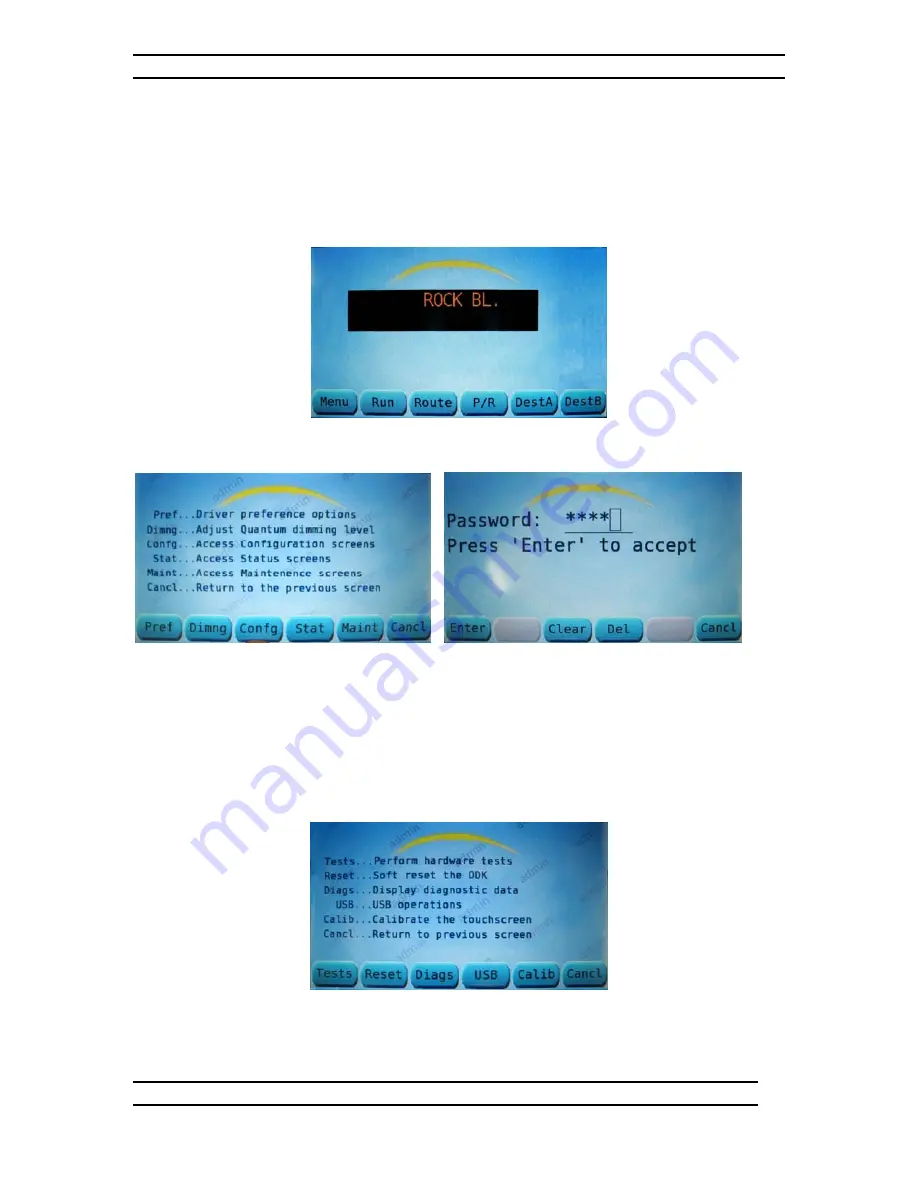
Press MENU at the default screen (see Fig. 7-5) to go to the Main Menu Screen. 


Figure 7-5. Default Screen  


Figure 7-6. Main Menu Screen                 Figure 7-7. Access Maintenance. Screen  

From the Main Menu Screen (see Fig. 7-6) press the MAINT Key to open the Access 
Maintenance Screens window – this will generate a request for a password. 
 
From the Access Maintenance Screens window (see Fig. 7-7) enter password (default is 
6511) via the keypad; then press ENTER to access the Maintenance Menu Screen (see 
Fig. 7-8). 


Figure 7-8. Maintenance Menu Screen


Summary of Contents for ODK4

Page 1: ...ERENCE GUIDE Luminator Publication 904700 Rev D REORDER INFORMATION FOR THIS DOCUMENT Specify Luminator Publication Number 904700 Operator s Display Keypad ODK4 QUICK REFERENCE GUIDE 2012 Luminator Te...

Page 2: ...QUICK REFERENCE GUIDE This manual contains proprietary information of Luminator Technology Group Reproduction disclosure or use without specific authorization of Luminator Technology Group is prohibi...

Page 3: ...ghtness Mode 10 4 1 3 Set Display Brightness Min Max Default Values 10 4 1 2 Set Display Brightness Level 11 SECTION 5 CONFIGURE EMERGENCY MESSAGE 12 5 1 Access Emergency Message Options 12 5 1 1 Conf...

Page 4: ...Configuration from Device 22 7 4 2 Load Message Listing from Device 23 7 4 3 Load Software from Device 24 7 5 Install Selected Files 25 SECTION 8 MAINTENANCE AND TROUBLESHOOTING 26 8 1 Introduction 2...

Page 5: ...ischarge and ground a circuit before touching it 9 NOTE Observe all safety regulations DO NOT SERVICE OR ADJUST ALONE Never reach into equipment with power applied Always have someone present who is c...

Page 6: ...ne channel for RS485 signals one channel for J1708 and a one channel RS232 interface Tx and Rx only J3 is a 15 pin female Dsub connector and provides one channel for J1939 one channel for Ethernet one...

Page 7: ...Auxiliary Input Adaptor Cable Assembly PN 508379 001 002 1 3 ODK4 Display Keypad The sign system is controlled through programmed instructions stored in ODK memory and through its liquid crystal displ...

Page 8: ...t power data adaptor cable J1 connector to the ODK4 J1 DB 9 connector Connect power data adaptor cable P1 connector to existing front sign cable Connect power data adaptor cable P2 connector to the ex...

Page 9: ...nfiguration of the ODK4 including software version hardware version model number options currently enabled including auto dim touchscreen communications protocols and alarm inputs Note If difficulties...

Page 10: ...These switches are permanently enabled All destination and public relations P R messages can be set and viewed from the ODK If enabled by transit authority programming the emergency message is activa...

Page 11: ...ht a letter then press SELCT to select it see Fig 3 5 Note To change a Route Number use the right arrow key to move the square cursor to the end of the string and then use the left arrow key to move c...

Page 12: ...message code number via the ODK number pad and press ENTER see Fig 3 7 Figure 3 7 P R Number Screen Note To change a P R code number or clear the message altogether use the left right arrow keys to hi...

Page 13: ...A Window Note To change a destination code use the right arrow key to move the square cursor to the end of the string and then use the left arrow key to move cursor back to the left to erase existing...

Page 14: ...ted Press MENU at the default screen see Fig 4 1 to access the Main Menu Screen see Fig 4 2 Figure 4 1 Default Screen Figure 4 2 Main Menu Screen Figure 4 3 Access Configuration Screens From the Main...

Page 15: ...re cursor box over Touchscreen Enabled box and then use Left Right arrow keys to check or un check box to enable disable feature 4 1 2 Set Auto Adjust Brightness Mode Use PREV NEXT buttons to hi light...

Page 16: ...see Fig 4 7 Figure 4 7 Drivers Pref Options Figure 4 8 Brightness Level Screen From the PREF Screen press the BRGHT key see Fig 4 7 From the Brightness Level screen see Fig 4 8 touch the brightness le...

Page 17: ...s Menu see Fig 5 1 press EMERG Key to access the Emergency Options Menu see Fig 5 2 5 1 2 Configure Emergency Message Options Auto Off From the Emergency Options Menu see Fig 5 2 press the MODE Key to...

Page 18: ...ither maintained or momentary type inputs 5 1 3 Configure Emergency Message Options Enable Input From the Emergency Options Menu see Fig 5 2 press the ENABL Key to access the Emergency Input Enable sc...

Page 19: ...Menu Screen Figure 6 1 Default Screen Figure 6 2 Main Menu Screen Figure 6 3 Access Maintenance Screen From the Main Menu Screen see Fig 6 2 press the MAINT Key to open the Access Maintenance Screens...

Page 20: ...the NOTIFY Key to access the Display System Notifications screen The normal Display System Notifications screen for a system with no faults should state No items in scrolled list see Fig 6 6 Figure 6...

Page 21: ...the IPS Software Compile the Message Listing for Flashcard MTU using the normal process The Transfer of the file to the USB stick is done outside of the IPS software 7 1 2 USB Stick Preparation Insert...

Page 22: ...gram After hi lighting the desired program press the OK key to start the message listing upload Figure 7 3 Remove USB Screen Figure 7 4 Message Database Update Status Screen Once the files are transfe...

Page 23: ...Figure 7 5 Default Screen Figure 7 6 Main Menu Screen Figure 7 7 Access Maintenance Screen From the Main Menu Screen see Fig 7 6 press the MAINT Key to open the Access Maintenance Screens window this...

Page 24: ...rt note the USB inserted Icon circled in the upper right corner see Fig 7 9 Figure 7 9 USB Operations Menu From the USB Operations menu see Fig 7 9 press the SAVE Key to access the Save to Device menu...

Page 25: ...e into USB Port Figure 7 12 USB Operations Menu From the USB Operations Menu see Fig 7 12 press the SAVE Key to access the Save to Device menu see Fig 7 13 Figure 7 13 Save to Device Menu From the Sav...

Page 26: ...ive into USB Port Figure 7 15 USB Operations Menu From the USB Operations menu see Fig 7 15 press the SAVE Key to access the Save to Device menu see Fig 7 16 Figure 7 16 Save to Device Menu From the S...

Page 27: ...res 7 5 through 7 8 From the Maintenance Menu see Fig 7 8 press the USB Key to access the USB Operations menu Remove USB port cover and insert the Config MTU Flashdrive into the USB Port note the USB...

Page 28: ...the Config MTU Flashdrive into the USB Port Figure 7 21 USB Operations Menu From the USB Operations menu see Fig 7 21 press the LOAD Key to access the Load From Device menu see Fig 7 22 Figure 7 22 L...

Page 29: ...tenance Menu see Fig 7 8 press the USB Key to access the USB Operations menu Remove USB port cover and insert the OS flashdrive into USB Port Figure 7 25 USB Operations Menu From the USB Operations me...

Page 30: ...indow From the Perform Upgrade window see Fig 7 29 press YES to begin the upgrade installation Figure 7 30 Remove USB Device Figure 7 31 System upgrade starting Remove the USB stick at the prompt see...

Page 31: ...s for more in depth sign troubleshooting If the problem is not solved contact your Luminator representative CAUTION BEFORE REMOVING OR REPLACING PARTS ENSURE POWER IS OFF TO SIGN SYSTEM Many ODK scree...

Page 32: ...s ENTER Update message listing contents to include the Emergency Mode displays Emergency mode shows momentarily on the exterior signs but goes away immediately ODK configured for the wrong emergency c...

Page 33: ...ies of quick pulses while communicating with the ODK If some signs are communicating please refer to the Sign troubleshooting guide of the appropriate sign manual USB Device Not Recognized Failure Rea...

Page 34: ...ODK4 QUICK REFERENCE GUIDE Luminator Technology Group 29 900 Klein Road Plano Texas 75074 USA Phone 972 424 6511 FAX 972 423 8515...

Reviews: