background image


English  - 

10 

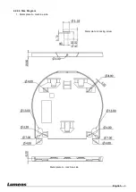
2.  Metal plate  B -  ceiling side 


Metal plate  B locking 

screw 

Metal plate  B locking 

bolt 

Metal plate  B -  ceiling side 

M3 threaded  hole 

M3 threaded  hole 


M3 threaded  hole 

Summary of Contents for VC-A50P

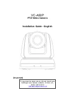
Page 1: ...C A50P PTZ Video Camera Installation Guide English Important To download the latest version of Quick Start Guide multilingual user manual software or driver etc please visit Lumens http www MyLumens com ...

Page 2: ...ke to turn on the back light compensation function 24 6 5 I would like to adjust the shooting angle of the lens 24 6 6 I would like to zoom in out images 24 6 7 I would like to adjust the focal length 24 6 8 I would like to adjust the AF speed 24 6 9 I would like to set the image mode 25 6 10 I would like to freeze images 25 6 11 I would like to rotate the image 25 6 12 I would like to change the ...

Page 3: ... product Lumens Digital Optics Inc hereby reserves the right to make changes to product specifications without prior notice The information in this file is subject to change without prior notice To fully explain or describe how this product should be used this manual may refer to names of other products or companies without any intention of infringement Disclaimer of warranties Lumens Digital Opti...

Page 4: ... Camera has been exposed to rain or water 2 Installation 2 1 For security considerations please make sure the standard hanging rack you bought is in line with UL or CE safety approbations and installed by technician personnel approved by agents 3 Storage 3 1 Do not place the HD Camera where the cord can be stepped on as this may result in fraying or damage to the lead or the plug 3 2 Never push ob...

Page 5: ...Class A limits for radio noise emissions from digital apparatus as set out in the interference causing equipment standard entitled Digital Apparatus ICES 003 of Industry Canada Cet appareil numerique respecte les limites de bruits radioelectriques applicables aux appareils numeriques de Classe A prescrites dans la norme sur le material brouilleur Appareils Numeriques NMB 003 edictee par l Industri...

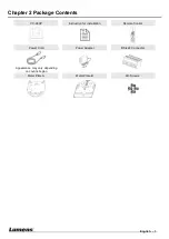
Page 6: ... 5 Chapter 2 Package Contents VC A50P Instruction for installation Remote Control Power Cord Power Adapter RS 422 Connector Appearance may vary depending on country region Metal Plate A Metal Plate B M3 Screws ...

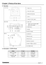
Page 7: ...3at PoE power 8 HDMI Output 9 3G SDI 10 OUTPUT Switch 11 IR SELECT 12 RS 232 output 13 RS 232 input 14 RS 422 Connection 15 Camera Address Selectors 16 SYSTEM Switch 3 2 Description of LED indicator Status Power Standby Startup in progress Green light Orange light In use Green light No indicator In standby mode No indicator Orange light Tally mode Red light Red light Front View Back View Bottom ...

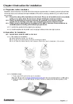
Page 8: ...e a proper place for installation of VC A50P in advance Please determine an installation place according to the following requirements 4 1 1 1 Confirm the position for the object to be captured 4 1 1 2 Confirm whether the VC A50P is set at a proper distance from other light sources 4 2 Instruction for installation 4 2 1 I would like to install VC A50P on the desk 4 2 1 1 Precautions for installati...

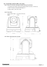
Page 9: ...during the installation 1 Accessories of VC A50P in the box metal plates A B M3 screw silver x 8 black x 2 2 Screw for locking on ceiling mounted hanger x 4 3 Drilling machine screw driver ladder 4 2 2 2 Camera Size Length x Width x Height 174 x 186 2 x 185 5 mm Weight 1 8 Kg 4 2 2 3 Max rotation dimension of camera ...

Page 10: ...English 9 4 2 2 4 Size Diagram 1 Metal plate A machine side Metal plate A machine side Metal plate A locking screw ...

Page 11: ...English 10 2 Metal plate B ceiling side Metal plate B locking screw Metal plate B locking bolt Metal plate B ceiling side M3 threaded hole M3 threaded hole M3 threaded hole ...

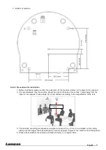
Page 12: ...distance of more than 1 meter away from the object to be captured Please adjust for a best distance according to the magnification of the lens 3 The machine including metal plates is weighed at about 2 5 kg If it is to be installed on the ceiling please use the hanger that has obtained UL security approval to prevent the machine from falling down 4 Please check whether the camera is installed secu...

Page 13: ... with 4 M3 silver screws 3 Lock the metal plate B on ceiling mounted hanger Caution 1 Please use the hanger that has obtained UL security approval 2 Please reserve the hole for the connecting wires of the camera 4 Combine the metal plate A and the metal plate B 1 Push the metal plate A up to the ceiling and then to the right to latch the metal plate B 2 And then secure with 2 M3 silver screws and ...

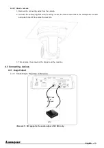
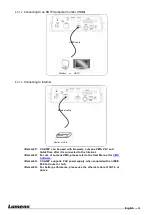
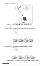
Page 14: ...ing loosen the three screws that fix the metal plates A and B and push to the left to remove the machine 3 Then remove the screws on the hanger and the machine 4 3 Connecting devices 4 3 1 Image Output 4 3 1 1 Connecting to PC video conference Remark 1 SDI supports the audio output of 48 KHz only HDMI Cable or SDI Cable MTU ...

Page 15: ...d QuickTime after it is connected to the Internet Remark 2 For use of Lumens VMS please refer to the User Manual for VMS Software Remark 3 VC A50P supports PoE power supply when coupled with an IEEE 802 3at router or hub Remark 4 For better performance please use the ethernet cable of CAT 6 or above Router or Hub Ethernet cable HDMI cable Monitor or HDTV ...

Page 16: ...with the computer 4 3 2 1 Connecting to one computer for connection between VCs RS 232 in out Remark With RS 232 in out at most 7 VCs can be connected 4 3 2 2 Connecting to one computer for connection between VCs RS 422 Remark Please refer to 8 2 RS 422 connection for the RS 422 connection instructions MIC or audio mixer Audio ...

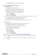
Page 17: ... completing settings press MENU to exit the OSD menu After completing setting and confirming IP address HDMI cable can be disconnected 4 3 3 2 Start Using Connect network cable to VC A50P network port to connect VC A50P to LAN Press MENU on the Remote Control to display the OSD menu Open the browser and enter the URL of VC A50P in the address bar e g http 192 168 100 150 default IP address Enter a...

Page 18: ...length Focus Auto Auto focus Freeze Freeze the screen Home Enter Go back to the main page Execute Info Status information L R Direction Set L R Direction Normal Menu Display OSD menu Mirror Rotate the image OFF Mirror Flip Rotate Pan Tilt Reset Clear the Pan Tilt setting Picture Switch image effect OFF NEG Black White Power Power Switch Preset Appoint an ID 0 9 to save the current position data Re...

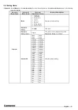
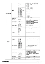
Page 19: ... Pri 4 Manual 5 White Board 6 Smooth Auto Exposure mode setting Exposure Comp On Off AE Level Exposure Comp Level 6 0 5 The value can be adjusted only after Exposure Comp is activated Shutter Pri 60 30 mode 50 25 mode Shutter priority setting 1 10000 1 10000 1 5000 1 5000 1 3000 1 3000 1 2500 1 2500 1 2000 1 1750 1 1500 1 1250 1 1000 1 1000 1 725 1 600 1 500 1 425 1 350 1 300 1 250 1 215 1 180 1 1...

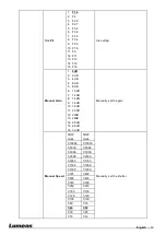
Page 20: ... 7 12 dB 8 14 dB 9 16 dB 10 18 dB 11 20 dB 12 22dB 13 24dB 14 26 dB 15 28 dB 16 30 dB Manually set the gain Manual Speed 60 30 mode 50 25 mode Manually set the shutter 1 10000 1 10000 1 5000 1 5000 1 3000 1 3000 1 2500 1 2500 1 2000 1 1750 1 1500 1 1250 1 1000 1 1000 1 725 1 600 1 500 1 425 1 350 1 300 1 250 1 215 1 180 1 150 1 120 1 120 1 100 1 100 1 90 1 75 1 60 1 50 1 30 1 25 1 15 1 12 ...

Page 21: ... F5 4 9 F6 3 10 F7 8 11 F9 12 F11 13 F13 14 F16 15 F18 Manually set the iris Gain Limit 1 8 dB 2 10 dB 3 12 dB 4 14 dB 5 16 dB 6 18 dB 7 20 dB Max limit value of electron gain Iris Limit 1 F1 6 2 F2 2 3 F3 2 4 F4 5 5 F6 3 6 F9 7 F13 8 F18 Max limit value of iris WDR 1 Off 2 1 3 2 4 3 5 4 6 5 WDR settings ...

Page 22: ...cture effect 1 Off 2 Neg 3 B W Set the picture effect Sharpness 0 C 15 Adjust the sharpness of the image 2D NR 1 Auto 2 Off 3 1 4 2 5 3 6 4 7 5 2D noise reduction settings 3D NR 1 Off 2 Low 3 Typ 4 Max 5 Auto 3D dynamic noise reduction settings Image Mode 1 Mode 1 2 Mode 2 3 Mode 3 4 Mode 4 5 Mode 5 6 Mode 6 7 Custom The user may customize his her desired image mode Image Mode Load 1 Mode 1 2 Mode...

Page 23: ... x20 Optical zoom limit Dig Effect Mirror 1 Off 2 Mirror 3 Flip 4 Mirror Flip Set the mode at which the image is turned Auto Focus AF Sensitivity 1 Low 2 Middle 3 High Select the AF triggering speed The higher the speed is the faster AF is triggered AF speed Fast Normal Focus speed after AF triggering AF Frame Full Frame Center AF frame setting when central area was set as AF frame focusing will b...

Page 24: ...ff When the function is enabled the screen will Freeze when Preset is executed Freeze will be released after Preset is completed Tally Lamp Enable Disable Turn on off the Tally Mode Language English Chinese Language Initial position Last MEM 1st Preset Output Mode 1 1080p 60 2 1080p 59 94 3 1080p 50 4 1080p 30 5 1080p 29 97 6 1080p 25 7 1080i 60 8 1080i 59 94 9 1080i 50 10 720p 60 11 720p 59 94 12...

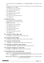
Page 25: ...just the shooting angle of the lens 1 Press Tilt or Tilt on the remote control to adjust the angle upward or downward 2 Press Pan or Pan on the remote control to adjust the angle to right or left 3 Press Pan Tilt Reset on the remote control to reset the angle to the center point 6 6 I would like to zoom in out images 6 6 1 Adjust image size 1 Press Fast on the remote control to zoom in images 2 Pr...

Page 26: ...e 6 Press or to select Fast Normal 7 Press MENU to exit 6 9 I would like to set the image mode 1 Press Picture on the remote control to switch Off Neg B W 6 10 I would like to freeze images 1 Press Freeze on the remote control to freeze the current image on the display 6 11 I would like to rotate the image 1 Press Mirror on the remote control to switch Off Mirror Flip Mirror Flip 6 12 I would like...

Page 27: ... switch or router 2 To connect directly through network cable the IP address of the computer should be changed so that it is on the same network segment as the camera for instance 192 168 100 x preset for camera Connection diagram Change network settings 7 2 2 Use the web browser 1 Open the IE browser and enter the URL of VC A50P in the address bar such as http 192 168 100 150 default IP address 2...

Page 28: ...www MyLumens com support php 2 After starting the software use search function to find out available VC A50P or add a known VC A50P IP address 3 Click VC A50P in the list and start operation after connecting to network 7 2 4 Use RTSP player In addition to browser and VMS other RTSP methods can be used for connection such as VLC and Quick Time RTSP connection address RTSP main stream h264 rtsp VC I...

Page 29: ...er is set up RTMP connection function can also be opened Please log into VC A50P webpage to change RTMP of network setting as described in 7 2 2 Use the Web Browser Remark To upload to YouTube for online viewing please refer to 7 3 9 Settings Audio Setting and turn on sound ...

Page 30: ...English Traditional Chinese and Simplified Chinese Remember password Remember the password so that you do not need to type it next time Login Log into the administrator screen on the website 7 3 2 Preview Screen 1 Rotate camera angle 2 Zoom in out 3 Preview window 4 Power off VC A50P 5 Apply Set preset 6 Switch to Full Screen 7 Logout VC A50PN 1 2 3 4 5 6 7 ...

Page 31: ...ssword and permission of new account Delete Delete new account Remark Reference for User Permissions User Type Admin Operator Viewer View images Y Y Y Settings Y Y N User accounts management Y N N 7 3 4 Settings Video Setting 1 Camera name Change camera name on this page 2 Select rate and encoding 3 Storage setting for advanced settings see 7 3 5 Settings Advanced Video Setting 1 2 3 4 VC A50P 1 2...

Page 32: ...ailable HIGH_QUALITY Higher image quality can be obtained SVC SVC opened encoding mode is applicable to RTSP series flow of 8601 8602 8603 and 8604 ports different refresh rate for different ports See remark 4 Encode Profile Encoded Information 5 Preset Save Remark SVC connection address rtsp VC IP Address Port h264 1 60Frame rtsp VC IP Address 8557 h264 E g rtsp 192 168 100 150 8557 h264 2 30Fram...

Page 33: ...t camera settings Please refer to 7 3 7 Settings Advanced Camera Setting 5 Preset Save 7 3 7 Settings Advanced Camera Setting 1 Exposure Mode Select exposure mode Exposure Comp Level Select exposure compensation level Gain Adjust gain restriction Iris Iris setting WDR WDR settings 1 2 3 4 VC A50P 5 4 1 2 3 ...

Page 34: ...ror Set automatic flip mode 7 3 8 Settings Picture Setting 1 Picture Effect Set the picture effect 2 2D NR 2D noise reduction settings 3 3D NR 3D dynamic noise reduction settings 4 Image Mode The user may customize his her desired image mode 5 Image Mode Load Adjustable when Image Mode is set to Custom similar to OSD 6 Black Level Adjustable when Image Mode is set to Custom similar to OSD 7 Gamma ...

Page 35: ...e is set to Custom similar to OSD 12 Sharpness Adjust the sharpness of the image 7 3 9 Settings Audio Setting 1 Turn on off sound 2 Set MIC In Line In 3 Adjust the Volume 4 Set audio delay 5 Set Encode Type ACC G 711 6 Set Encode Sample rate 7 Preset Save 7 3 10 Settings Date Time Setting VC A50P 1 3 2 VC A50P 1 2 4 5 6 3 ...

Page 36: ...ff please turn off DHCP function using VC A50P screen menu and for setting of each item of screen menu see 5 2 Setting Menu 2 Set RTMP Set connection address of RTMP depending on RTMP Server setting 3 Set RTSP Enable Disable Multicast Remark It is suggested to enable Multicast when the number of users online watching the live image simultaneously is more than 4 4 Set MPEG TS Set MPEG TS format 5 S...

Page 37: ...English 36 7 3 12 Maintenance 1 Firmware Upload 2 Error Log 3 Factory Reset 4 Set ONVIF command as standard or custom 5 NDI registration information VC A50P 1 21 31 41 5 ...

Page 38: ...1 OUTPUT Switch Output Mode Setting Output Mode Setting 1920x1080 60p 1920x1080 50p 1920x1080 30p 1920x1080 25p 1920x1080 60i 1920x1080 50i 1280x720 60p 1280x720 50p 1080 59 94p 1080 59 94i 1080 29 97p 720 59 94p 8 1 2 IR SELECT ID Setting 1 2 3 8 1 3 Camera Address Selector Setting Function Descriptions 0 7 ID 0 7 8 9 Reserved ...

Page 39: ...ff ON On DIP 3 Communication baud rate selector OFF 9600 ON 38400 DIP 4 Reserved 8 2 RS 422 Connection 8 2 1 RS 422 Pin Description Pin NO Function 1 RXD OUT 2 RXD OUT 3 TXD OUT 4 TXD OUT 5 GND 6 RXD IN 7 RXD IN 8 TXD IN 9 TXD IN Note Please connect IN to OUT when connecting to SONY products For non SONY products it may be necessary to connect IN to OUT ...

Page 40: ...y the arrow in the figure below 2 Peel off a section of copper wire AWG Nos 28 to 18 and insert it into the connector hole then use flat screw driver to fix it 3 Insert the wired RS 422 connector back to the camera Now the connection is completed Note When RS 422 connection is being used do not use RS 232C connection ...

Page 41: ...e power cord and turn on the machine to change the setting 5 VC A50P cannot be operated by remote control 1 Please confirm if the Camera Select on the remote control can be used together with the IR Select on VC A50P 2 Please prevent VC A50P from direct sunshine 3 Make sure the energy saving bulb and the IR touch screen are as far as possible in order to avoid interference 4 When several VC A50P a...

Page 42: ...ormation Supplier Lumens Integration Inc 4116 Clipper Court Fremont CA 94538 United States e mail support mylumens com FCC Compliance Statement This device complies with Part 15 of the FCC Rules Operation is subject to the following two conditions 1 This device may not cause harmful interference and 2 this device must accept any interference received including interference that may cause undesired...

Reviews: