background image

Connecting Paging, Call Reporting (SMDR),
and Music-On-Hold Devices

Only steps for connection to the processor module are

provided here. See the manufacturer’s instructions for
more information on installing and using these devices.

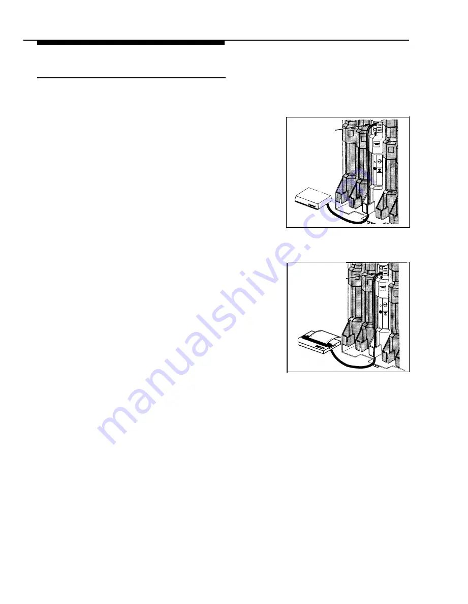
Paging System

PAGE Jack

If you connect a paging system from a manufacturer

other than Lucent Technologies, a paging interface may

be required.

1

Insert the modular plug into the PAGE jack on the
primary processor module.

2

Route the cord as you did for line and extension

cords, then connect it to the paging system.

Paging System

(optional)

Call Reporting (SMDR) Printer

1

Insert one end of a D8W modular cord into the SMDR
jack on the primary processor module.

2

Plug the other end into a 355A adapter, then plug the
adapter into the printer’s RS-232C serial port.

SMDR Jack

Call Accounting
Terminal Printer

(optional)

16    

Installation Procedures

Summary of Contents for PARTNER II Release 4.1

Page 1: ...Lucent Technologies Bell Labs Innovations PARTNER II Communications System Release 4 1 Installation 518 455 333 Comcode 107879223 Issue 2 August 1996 ...

Page 2: ...tions services You are responsible for the security of your system There may be a risk of toll fraud associated with your telecommunications system You are responsible for programming and configuring your equipment to prevent unauthorized use Your system manager should read all documents provided with this product to fully understand the features that can introduce the risk of toll fraud and the s...

Page 3: ...nd Modules Connecting Lines and Extensions Connecting Caller ID Display Devices Assembling System Phones Desk Mounting Wall Mounting Connecting and Testing Telephones Connecting Paging Call Reporting SMDR and Music On Hold Devices Paging System Call Reporting SMDR Printer Music on Hold Audio Source Connecting a PARTNER CA48 Intercom Autodialer Equipment Upgrades Adding New Modules Replacing System...

Page 4: ...three wire grounding type plug This is a safety feature DO NOT defeat the safety purpose of the grounding type plug DO NOT staple or otherwise attach the power supply cord to building surfaces CAUTION DO NOT block or cover the ventilation slots and openings They prevent the product from overheating DO NOT place the product in a separate enclosure unless proper ventilation is provided Additional Sa...

Page 5: ...e sure that your installation meets all electrical and environmental requirements If your company already has modular jacks for all outside lines and extensions you may be able to use the existing wiring to install the system hardware and connect telephones to the system yourself To have a Lucent Technologies service technician install and customize your system or change existing wiring call 1 800...

Page 6: ...n a license from a third party such as ASCAP or BMI The Magic on Hold system does not require such a license For more information see Music on Hold Audio Source later in this guide Extensions Various devices including system phones and industry standard devices can be connected to the modular wall jacks The modular wall jacks connect to the extension jacks in the control unit by way of the buildin...

Page 7: ...L UNIT Primary Carrier Expansion Carrier Extension 10 Extension 17 EXTENSIONS Extension 14 Extension 18 Extension 11 Extension 15 Extension 12 Extension 19 Extension 16 Extension 13 An Example System Setup 3 ...

Page 8: ...le Figure 1 Required Parts You will need to obtain four 12 screws of the appropriate type for the wall and weight of each carrier a carrier with four 206 modules and a processor module weighs approximately 27 5 pounds or 12 3 kilograms You also need two lengths of 12 AWG or 14 AWG solid copper wire not to exceed 25 feet or 7 6 meters each for grounding In addition if you need modular telephone cor...

Page 9: ...t the following telephones and devices to the system PARTNER model MLS modeI MDC 9000 and MDW 9000 System Phones System phones require at least two pair wiring and are compatible with Lucent Technologies 4 pair SYSTIMAX wiring Call Assistant Intercom Autodialers with Busy Indication PARTNER CA48 for PARTNER model phones or MLS CA24 for MLS model phones You can connect an Intercom Autodialer to the...

Page 10: ...IL System This device connects to the system through extension jacks Do not connect PARTNER MAIL to extension 10 16 22 28 34 40 46 or 52 to keep them available for power failure use The PARTNER MAIL VS System This device which physically resembles a 206 module resides in the control unit Call Reporting Devices You can connect either a serial printer or a call accounting device such as Lucent Techn...

Page 11: ...ct two standard devices together you must use a Lucent Technologies 267F2 Bridging Adapter see Using a Bridging Adapter below Using a Direct Connection Figure 2 shows how to connect a standard device directly to a system phone using the phone s built in auxiliary jack Figure 2 is for illustration purposes only the placement of the jacks on your phone may differ System Phone Plug line into jack lab...

Page 12: ... against the wall If you are also installing the expansion carrier plan to install it to the right of the primary carrier leaving 6 to 24 15 2 to 61 cm between the carriers Using the four screw keyholes in the backplane as a template mark screw locations on the wall Start four 12 screws leaving the screw heads approximately 1 4 64 cm away from the wall Slip the backplane onto the screws then tight...

Page 13: ...lug the ends of the expansion cable into the two processor modules and tighten the screws Route both ends of the cable through the hooks on the fronts of the modules The colored plastic filters on the expansion cable should rest just below the bottom edge of the carriers Module Pull out the main circuit breakers on both carriers or move the on off switch to the off position O depending upon which ...

Page 14: ...up the control unit If multiple lights are out power down the control unit reseat the leftmost module that has a light out then power up the control unit B If the lights are still out call for support as instructed on the inside front cover of this guide Connecting Lines and Extensions If extensions are not wired to any modular jacks call a qualified service technician 1 Network Interface 2 A B C ...

Page 15: ...ress the wires Gather the line and extension cords hanging below the hooks of the first two modules and twist tie or wire wrap them Repeat for the remaining cords Place each bundle of wires in the indentations cut out of the bottom edge of the backplanes Before installing the cover make sure all modules are seated properly in the carrier The cover will not fit if the modules are not seated properl...

Page 16: ...ve additional wiring runs installed call a qualified technician 1 2 3 Insert a Lucent Technologies 267F2 Bridging Adapter into the network interface jack associated with the line that has Caller ID service A B C A B C D E Plug one end of a line cord into a jack in the bridging adapter Plug the free end of the line cord into the appropriate line jack in the control unit Route the cord as you did fo...

Page 17: ...he tabs to lock the stand into one of the three positions provided by the openings in the back of the phone The height of the stand is adjustable to three positions low medium and high The phone height can be adjusted by moving the locking tabs to a different position Turn the phone over Remove the plastic cover from the phone Label the button sheet to show any programmed lines or button features ...

Page 18: ...on the wall plate using the keyholes on the base of the stand For proper mounting the wall plate must be a Lucent Technologies 630B connecting block A Plug one end of the telephone cord into the jack in the center of the wall plate B Plug the other end of the telephone cord into the LINE jack on the bottom of the telephone C Wrap any excess cord around the cord wrap posts on the bottom inside of t...

Page 19: ...d its mounting cord is loose use a Lucent Technologies D2R mounting cord instead To install two phones or other devices on a single extension jack see Combination Extensions earlier in this guide 2 A B C Test the telephone for proper operation To test the power and lights on a system phone while the phone is idle press and hold the button for five seconds Before releasing the button lift the hands...

Page 20: ...ies a paging interface may be required 1 Insert the modular plug into the PAGE jack on the primary processor module 2 Route the cord as you did for line and extension cords then connect it to the paging system Paging System optional Call Reporting SMDR Printer 1 Insert one end of a D8W modular cord into the SMDR jack on the primary processor module 2 Plug the other end into a 355A adapter then plu...

Page 21: ...nal Inc at 1 800 446 5366 Or you can purchase a Magic On Hold system from Lucent Technologies which does not require you to obtain a license 1 2 3 4 First set the unit s volume to the lowest setting Use a flathead screwdriver to turn the volume control on the processor module counterclockwise until it stops Insert an RCA phono plug into the MUSIC ON HOLD jack on the primary processor module Route ...

Page 22: ...PARTNER CA48 Intercom Autodialer Plug the other end clear tinted of the power cord into the J2 jack on the adapter Plug the power unit into an electrical outlet Plug the phone s modular telephone cord into the OUT jack on the bottom of the autodialer Arrange the autodialer on the desk next to the phone Remove the plastic cover from the autodialer and label the button sheet with employee names Plac...

Page 23: ...ot to break the tabs that attach the cover to the backplane Before you insert the new module make sure that all 400 or 200 modules are installed to the right of all 206 modules Push slowly but firmly in the center of the module until the module locks into place and is attached to the rear of the backplane Do not force the module If the module does not insert easily remove it clear any obstruction ...

Page 24: ...ol unit Place the cover over the modules and make sure it fits firmly in place Tighten the screw on the lower front of the cover Replacing System Modules WARNING Before starting disconnect the power cord from the power jack on the backplane 4 A B 5 A B C D 1 A B C To power down the control unit pull out the the main circuit breakers on both carriers or move the on off switch to the off position O ...

Page 25: ...ect the power cord To power up the control unit push in the main circuit breakers or move the on off switch to the on position l Check all green lights on the fronts of the modules If all the lights are lit installation is complete otherwise A B A B C D If a single light is out power down the control unit reseat the module then power up the control unit If multiple lights are out power down the co...

Page 26: ...Ibs or 1 8 kgs and Weights 206 module 11 D x 17 H x 1 5 W or 27 9 x 43 2 x 3 8 cm 4 5 Ibs or 2 0 kgs approx 400 module 11 D x 17 H x 1 5 W or 27 9 x 43 2 x 3 8 cm 4 0 Ibs or 1 8 kgs Backplane cover 12 D x 19 H x 11 W or 30 5 x 48 3 x 27 9 cm 5 5 Ibs or 2 5 kgs PARTNER 34D phone 9 8 D x 3 75 H x 9 3 W or 24 9 x 9 5 x 23 6 cm 2 7 lbs or 1 2 kgs PARTNER 18D phone 9 8 D x 3 75 H x 7 9 W or 24 9 x 9 5 ...

Page 27: ...not controlled by a switch using supplied 7 foot 2 1 meter cords For proper ventilation and easy replacement of modules provide at least 6 15 2cm clearance at the top and sides and 2 feet 0 6 meters at the front and bottom of the control unit Operating temperature 32 to 104 F 0 to 40 C not in direct sunlight Humidity 15 90 noncondensing Locate in an area free of excess moisture corrosive gases dus...

Page 28: ... telecommunications equipment single line phones fax machines answering machines etc 1 pair 2 wire mounting cords Lucent Technologies D2R mounting cords recommended Bridging adapter Lucent Technologies 267F2 Range 1 000 feet 305 meters for system phones 3 000 feet 915 meters for standard devices Safety U S Meets UL 1459 Issue 2 Requirements Canada Meets CSA C22 2 225 All other countries Meets IEC9...

Page 29: ...Lucent Technologies 518 455 333 Comcode 107879223 Issue 2 August 1996 ...

Reviews: