


Digital
Video
Recorder
Quick
Start
Guide
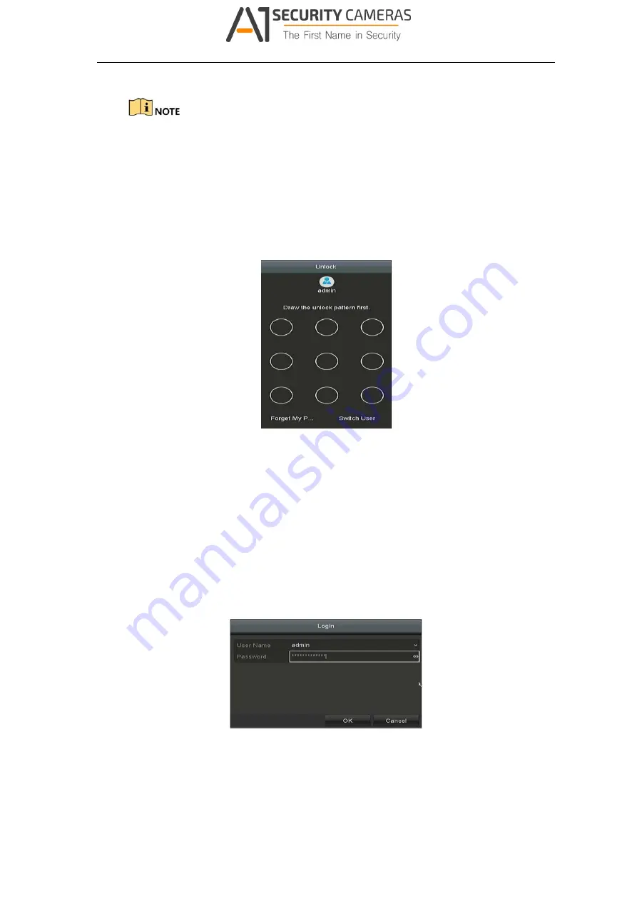
Connect
at
least
4
dots
to
draw
the
pattern.
Each
dot
can
be
connected
for
once
only.
Step
2
Draw
the
same
pattern
again
to
confirm
it.
When
the
two
patterns
match,
the
pattern
is
configured
successfully.
Step
3
You
can
use
the
configured
unlock
pattern
for
future
login.
Figure
3
‐
9
Draw
the
Unlock
Pattern
3.5
Login
and
Logout
3.5.1
User
Login
Purpose:
If
DVR
has
logged
out,
you
must
log
in
to
the
device
before
operating
the
menu
and
other
functions.
Step
1
Select
the
User
Name
in
the
dropdown
list.
Figure
3
‐
10
Login
Step
2
Input
Password
.
Step
3
Click
OK
to
log
in.
20
Available from A1 Security Cameras
www.a1securitycameras.com email: [email protected]


