background image

Digital Video Recorder Quick Start Guide 

18 


STRONG  PASSWORD  RECOMMENDED

–We highly recommend you create a strong 

password of your own choosing (Using a minimum of 8 characters, including at least 

three of the following categories: upper case letters, lower case letters, numbers, and 

special characters.) in order to increase the security of your product. And we 

recommend you reset your password regularly, especially in the high security system, 

resetting the password monthly or weekly can better protect your product.


Step 2


Click 

OK

 to save the password and activate the device. 


Clear-text password is supported. Click the 

  icon and you can see the clear 

text of the password. Click the icon again and the content of the password 
restores invisible. 


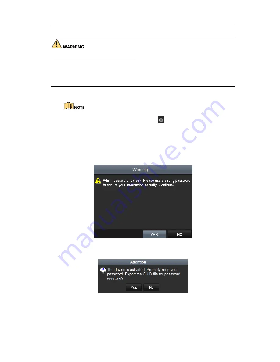
For the old version device, if you upgrade it to the new version, the following 
dialog box will pop up once the device starts up. You can click 

YES 

and follow 

the wizard to set a strong password.   


Figure 3-4


Warning of Weak Password 

Step 3


After the device is activated, the Attention box pops up as below. 


Figure 3-5


Attention 

Step 4


(Optional) Click 

Yes

 to export GUID. The Reset Password interface pops up. Click 

Export

 to export GUID to the USB flash disk for password resetting. 

Summary of Contents for LTD8304K-ET

Page 1: ...Digital Video Recorder Quick Start Guide ...

Page 2: ... 4 HDD Storage Calculation Chart 14 Chapter 3 Menu Operation 16 3 1 Menu Structure 16 3 2 Startup and Shutdown 16 3 3 Activating Your Device 17 3 4 Using the Unlock Pattern for Login 19 3 5 Login and Logout 20 3 5 1 User Login 20 3 5 2 User Logout 22 3 6 Using the Setup Wizard 23 3 7 Viewing Signal Input Status 23 3 8 Network Settings 25 3 9 Adding IP Cameras 25 3 10 Live View 27 3 11 Recording Se...

Page 3: ... of professionals Legal Disclaimer REGARDING TO THE PRODUCT WITH INTERNET ACCESS THE USE OF PRODUCT SHALL BE WHOLLY AT YOUR OWN RISKS OUR COMPANY SHALL NOT TAKE ANY RESPONSIBILITES FOR ABNORMAL OPERATION PRIVACY LEAKAGE OR OTHER DAMAGES RESULTING FROM CYBER ATTACK HACKER ATTACK VIRUS INSPECTION OR OTHER INTERNET SECURITY RISKS HOWEVER OUR COMPANY WILL PROVIDE TIMELY TECHNICAL SUPPORT IF REQUIRED S...

Page 4: ...ference 2 This device must accept any interference received including interference that may cause undesired operation EU Conformity Statement This product and if applicable the supplied accessories too are marked with CE and comply therefore with the applicable harmonized European standards listed under the EMC Directive 2014 30 EU the LVD Directive 2014 35 EU the RoHS Directive 2011 65 EU 2012 19...

Page 5: ...nventions The symbols that may be found in this document are defined as follows Symbol Description Provides additional information to emphasize or supplement important points of the main text Indicates a potentially hazardous situation which if not avoided could result in equipment damage data loss performance degradation or unexpected results Indicates a hazard with a high level of risk which if ...

Page 6: ...m the device turn off the power at once and unplug the power cable and then please contact the service center Preventive and Cautionary Tips Before connecting and operating your device please be advised of the following tips Ensure unit is installed in a well ventilated dust free environment Unit is designed for indoor use only Keep all liquids away from the device Ensure environmental conditions ...

Page 7: ... condition is met Tx Rx TX RX indicator flickers green when network connection is functioning normally 2 USB Interfaces Universal Serial Bus USB ports for additional devices such as USB mouse and USB Hard Disk Drive HDD 3 Composite Keys 1 MENU Enter numeral 1 Access the main menu interface 2 ABC F1 Enter numeral 2 Enter letters ABC The F1 button when used in a list field will select all items in t...

Page 8: ...utput 4 SHIFT Switch between the numeric or letter input and functions of the composite keys Input letter or numbers when the light is out Realize functions when the light is red 5 Control Buttons Directional buttons In menu mode the direction buttons are used to navigate between different fields and items and select setting parameters In playback mode the Up and Down buttons are used to speed up ...

Page 9: ...t Rear Panel 1 Figure 1 2 Rear Panel of LTD83XXK ST Rear Panel 2 Figure 1 3 Rear Panel of LTD85XXK ST Table 1 2 Description of Rear Panel No Item Description 1 VIDEO IN BNC interface for TVI and analog video input 2 USB Port Universal Serial Bus USB port for additional devices 3 VIDEO OUT BNC connector for video output 4 HDMI HDMI video output connector 5 VGA DB15 connector for VGA output Display ...

Page 10: ... Start Guide 9 8 AUDIO IN RCA connector 9 RS 485 Connector for RS 485 devices 10 Power Supply DC 12V power supply 11 Power Switch Switch for turning on off the device 12 GND Ground 13 Alarm In Out Connector for alarm input output ...

Page 11: ...ounded Environmental temperature should be within the range of 10 to 55º C 14 to 131º F Environmental humidity should be within the range of 10 to 90 2 2 Hard Disk Installation Before you start Before installing a hard disk drive HDD please make sure the power is disconnected from the DVR A factory recommended HDD should be used for this installation One or two SATA hard disks can be installed dep...

Page 12: ...e end of the data cable to the motherboard of DVR and the other end to the HDD Figure 2 2 Connect Data Cable Step 3 Connect the power cable to the HDD Figure 2 3 Connect Power Cable Step 4 Place the HDD on the bottom of the device and then fasten the screws on the bottom to fix the HDD ...

Page 13: ...Digital Video Recorder Quick Start Guide 12 Figure 2 4 Fix Hard Disk Step 5 Re install the cover of the DVR and fasten screws ...

Page 14: ...om the RS 485 terminal block Step 2 Press and hold the orange part of the pluggable block insert signal cables into slots and release the orange part Ensure signal cables are in tight Step 3 Connect A on PTZ to D on terminal block and B on controller to D on terminal block Fasten stop screws Step 4 Connect pluggable block back into terminal block Make sure both the controller and DVR are grounded ...

Page 15: ...gital Video Recorder Quick Start Guide 14 2 4 HDD Storage Calculation Chart The following chart shows an estimation of storage space used based on recording at one channel for an hour at a fixed bit rate ...

Page 16: ...84K 168M 448K 196M 512K 225M 640K 281M 768K 337M 896K 393M 1024K 450M 1280K 562M 1536K 675M 1792K 787M 2048K 900M 4096K 1 76G 8192K 3 52G 16384K 7 03G Please note that supplied values for storage space used is just for reference The storage values in the chart are estimated by formulas and may have some deviation from actual value ...

Page 17: ...ice The Power button on the front panel should be red indicating the device is receiving the power Menu Export Manual HDD Camera Maintenance Shutdown Record Configuration Playback Normal Record General Schedule Camera General System Info Logout Event Advanced Parameters OSD Network Log Information Shutdown Advanced Image Import Export Reboot Holiday PTZ Upgrade Motion Live View Default Privacy Mas...

Page 18: ...nd recording To shut down the DVR Step 1 Enter the Shutdown menu Menu Shutdown Figure 3 2 Shutdown Step 2 Select the Shutdown button Step 3 Click the Yes button 3 3 Activating Your Device Purpose For the first time access you need to activate the device by setting an admin password No operation is allowed before activation You can also activate the device via Web Browser SADP or client software St...

Page 19: ...oduct Step 2 Click OK to save the password and activate the device Clear text password is supported Click the icon and you can see the clear text of the password Click the icon again and the content of the password restores invisible For the old version device if you upgrade it to the new version the following dialog box will pop up once the device starts up You can click YES and follow the wizard...

Page 20: ...ure 3 7 Duplicate the Password 3 4 Using the Unlock Pattern for Login For the Admin user you can configure the unlock pattern for device login After the device is activated you can enter the following interface to configure the device unlock pattern Step 1 Use the mouse to draw a pattern among the 9 dots on the screen Release the mouse when the pattern is done Figure 3 8 Draw the Pattern ...

Page 21: ...tch the pattern is configured successfully Step 3 You can use the configured unlock pattern for future login Figure 3 9 Draw the Unlock Pattern 3 5 Login and Logout 3 5 1 User Login Purpose If DVR has logged out you must log in to the device before operating the menu and other functions Step 1 Select the User Name in the dropdown list Figure 3 10 Login Step 2 Input Password Step 3 Click OK to log ...

Page 22: ...times the account will be locked for 60 seconds For the operator if you have entered the wrong password for 5 times the account will be locked for 60 seconds Figure 3 11 User Account Protection for the Admin Figure 3 12 User Account Protection for the Operator Step 4 Optional If you forget the password click Forget Password to pop up the Import GUID interface Figure 3 13 Import GUID 1 Select the G...

Page 23: ...to IP cameras that are connected with default protocol Click Yes to duplicate the password or No to cancel it Figure 3 16 Duplicate the Password If you want to retrieve the password when you forget it you must export the GUID file first Once the password is reset the GUID file becomes ineffective You can export a new GUID file 3 5 2 User Logout Purpose After logging out the monitor turns to the li...

Page 24: ...p Wizard starts once the device has loaded Check the checkbox to enable Setup Wizard when device starts Click Next to continue the setup wizard Follow the guide of the Setup Wizard to configure the system resolution system date time network settings HDD management record settings etc Figure 3 18 Wizard 3 7 Viewing Signal Input Status 5 MP long distance transmission is available for LTD85XXK ST ser...

Page 25: ...nnels and types and the connectable maximum IP camera number Step 3 Optional You can enable 5 MP Long Distance Transmission for the Turbo HD and AHD signal input Follow the steps below to enable the function 1 Click to enter the 5 MP Long Distance Transmission Settings interface Figure 3 20 5 MP Long Distance Transmission Settings 2 Check the checkbox to enable 5 MP Long Distance Transmission of t...

Page 26: ...s available you can check the checkbox of DHCP to automatically obtain an IP address and other network settings from that server Step 4 After having configured the general settings click the Apply button to save the settings 1 self adaptive 10M 100M 1000M network interface is provided for LTD83XXK ET and LTD85XXK ST series DVR If DHCP is enabled you can check the checkbox of Enable DNS DHCP or unc...

Page 27: ...m the right click menu in live view mode or click Menu Camera Camera to enter the IP camera management interface Figure 3 22 Add IP Camera Step 2 Select the IP camera from the list and click the button to add the camera with the same admin password of the DVR s Step 3 Optional Check the checkbox of Enable H 265 For Initial Access for the connected IP camera supporting H 265 Then the IP camera will...

Page 28: ...ring motion detection VCA or sensor alarm Record manual record continuous record motion detection VCA or alarm triggered record Alarm and Record Event Exception event and exception information appears at the lower left corner of the screen 3 11 Recording Settings Before you start Make sure that the disk has already been installed If not please install a disk and initialize it You may refer to the ...

Page 29: ... periods external file search picture Step 1 Enter playback interface Menu Playback Or select Playback from the right click menu Step 2 Check the checkbox of channel s in the channel list and then double click to select a date on the calendar Step 3 Optional Use the toolbar in the bottom part of Playback interface to control playing progress Figure 3 24 Playback Interface For LTD85XXK ST series DV...

Page 30: ...Digital Video Recorder Quick Start Guide 29 Figure 3 25 Show VCA Information in Smart Playback Step 4 Optional Select the channel s to execute simultaneous playback of multiple channels ...

Page 31: ...t access to the device via web browser You may use one of the following listed web browsers Internet Explorer 6 0 Internet Explorer 7 0 Internet Explorer 8 0 Internet Explorer 9 0 Internet Explorer 10 0 Apple Safari Mozilla Firefox and Google Chrome The supported resolutions include 1024 768 and above Step 1 Open web browser input the IP address of the device and then press Enter Step 2 Login to t...

Page 32: ...ecially in the high security system resetting the password monthly or weekly can better protect your product If the device is already activated enter the user name and password in the login interface and click the Login button Figure 4 2 Login Step 3 Install the plug in before viewing the live video and managing the camera Please follow the installation prompts to install the plug in You may have ...

Reviews: