Threshold
Allows to set the threshold level: if the signal goes below this threshold the Noise Gate reduces
the level. The editing values are within the following ranges: +8dBu -60dBu, with 2dBu steps.
Allows to adjust the amplification of the signal fed in through Inputs A and B.
Editing values are in the range
~
, with
steps.
+6dB
-30dB
0.5dB
I n p u t
G a i n
I N A
G A I N
- 2 . 5 d B
5.3.2 Input Noise Gate
N o i s e
G a t e
Note
INPUT LEVEL A-B
CLIP
: Setting the input signal of a digital unit is particularly important, much more than on an
analog unit, as any saturation of the A/D converter due to an excessively high input signal causes
a typical particularly distinct noise. To achieve a good signal/noise ratio, i.e. an up-front distortion
free signal, feed a signal in on the MAXIDRIVE3.4+'s input and watch the
LED
ladders. Keep the signal quite high, but make certain the red
LED doesn't light on continually.
Noise reduction filter on the inputs
Allows to cut or reduce the background noise generated by the unit connected to the
processor's inputs (the mixer, for example). The filter is active when the input signal is below
a certain threshold and reduce its level cutting the undesired background noises.
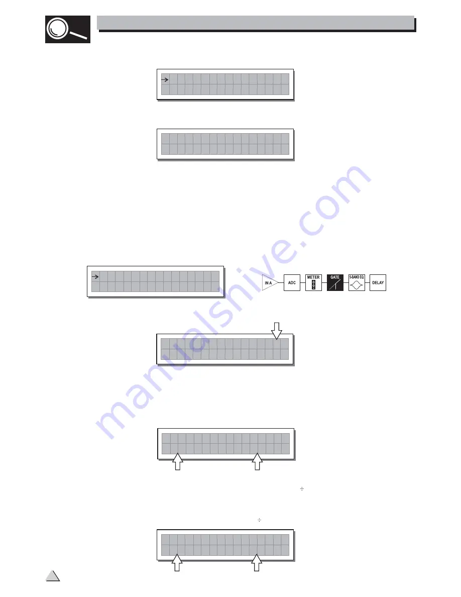
The following editable parameters are available, in two different pages:
a. Noise Gate ON/OFF
b. Reaction times
Allows to set the Noise Gate attack and release times.
- ATTACK (AT)
: is the time needed by the filter to bring back the signal to its normal level when
it goes above the threshold.
- RELEASE (RL)
: is the time needed by the filter to cut the signal once it goes below the
threshold.
I N A
G a t e
5
.
0
n
O
1 .
T
0
A
m s
R L
S
0
I N A
G a t e
5
.
0
n
O
1 .
T
0
A
m s
R L
S
0
The editing values are within the following ranges: 0dBu -80dBu, with variable steps.
Rage
Allows to set the amount of the signal level reduction.
I N A
G a t e
0
8
0
n
O
R -
H
-
T
0 .
R G
6
0
.
5. THE MENU MAP CONFIGURATION DESCRIPTION
14
5.3.1 Input Gain
Input gain control.


