background image


Preparing the baler for transportation  

 
Before transporting your baler please perform these basic checks to avoid injury to 
persons or damage to your machine. 
 

  Check that all doors are closed and latched 


  Any trailing cables are tidied away 


  The oil bung is in the tank 


  All parts are bolted down parts are tight 


  Any loose parts are placed inside the baler 


Moving the baler 

 
Moving the baler should only be done via the use of a forklift or p

allet truck. Do not ‘drag’ 

the machine around by hand as this could cause injury to you, or damage to the machine. 
  
When lifting a baler the forks or pallet truck should be inserted in the gap in the base as 
shown below (approx weights 500 - 600

kg’s). 


Summary of Contents for V5HD

Page 1: ...SERIAL NO INSTALLATION DATE CE Certified EN16500 Compliant www lsmltd com Keep these instructions for future use OPERATOR INSTRUCTION MANUAL V5HD CAN AND BOTTLE BALER ...

Page 2: ...2 ...

Page 3: ...rranty Warranty Registration Forms 15 Warranty 19 Safety General Safety 20 Safety Checklist 20 Optional Extras Consumables 21 Machine decal explaination 22 Operation Instructions A Preparation prior to loading 23 24 B Loading the Baler Instructions Diagram 23 C Tying and removing the bale 25 26 Kicker operation 27 Troubleshooting 28 Care and Maintenance 29 Parts List 30 31 Terms and Conditions 32 ...

Page 4: ...4 ...

Page 5: ...e faxed to LSM Failure to do so can result in loss of warranty for your machine This manual has been carefully written to help you maintain the condition of your machine Please adhere to the recommended maintenance instructions to prolong the life of your machine Keep safety in mind at all times Failure to do so could result in personal injury or damage to your machine All information illustration...

Page 6: ... The oil bung is in the tank All parts are bolted down parts are tight Any loose parts are placed inside the baler Moving the baler Moving the baler should only be done via the use of a forklift or pallet truck Do not drag the machine around by hand as this could cause injury to you or damage to the machine When lifting a baler the forks or pallet truck should be inserted in the gap in the base as...

Page 7: ...r via the bolt holes provided on both sides of the base and the top this will provide extra stability during transport UNDER NO CIRCUMSTANCES SHOULD A PERSON OR BODY PART BE UNDER THE MACHINE DURING LOADING OR MOVING When the baler or balers are in position on the trailer they should be tied down using a ratchet strap One strap across the top of the baler is sufficient to keep it fixed during tran...

Page 8: ...t the machine via the base page 6 Do not attempt to move the machine by hand as this could cause injury to you or damage the machine Fix your machine to a solid level surface to avoid movement while in operation Brackets are provided with to the baler so it can be screwed into a wall or sound concrete ground Use with proper fixings M12 rawl bolts and bolt down on 2 corners as shown in below B a l ...

Page 9: ...and understood all of the safety and operational procedures Ensuring that personnel have access to the operator s manual at all times Ensuring that the electrical cable from the machine to the mains is located in a safe position out of harm s way and does not pose any hazards to the operator Ensuring that the baler is plugged directly to the mains supply without the use of an extension cable Suppl...

Page 10: ...ng Ltd will not be held responsible for any loss or damage resulting from machine applications other than those specified Any other use the machine may be put to is entirely at the owners operators risk The designated use of an LSM Material Baler precludes that the operation maintenance and repair instructions as given by the manufacturer will be strictly fulfilled Any alterations made to this mac...

Page 11: ...11 Safe Operation Zone Ejection ...

Page 12: ...12 Emergency Stop Location ...

Page 13: ...e Time 35 seconds Door Type Swinging Door Standard Bale Size Indicator Internal No Of Rams 1 Technical Motor Type 220 S Phase 1 5Kw motor Operator Controls 24V Standard Auto Shut Down Standard Operating Cycle Double Acting Emergency Stop Standard Cycle Time 35 Seconds ...

Page 14: ...EC V5HD Overall Height 2015mm Overall Width 765mm Overall Depth 1080mm Machine Depth 575mm F Machine Weight Approx 415kg BALE SPEC F Height 700mm G Width 600mm H Depth 400mm I Bale Weight Approx cardboard 20 60kg J Bale Weight Approx Metal 60 100kg ...

Page 15: ...IGN IF YOU HAVE RECEIVED BOTH OF THESE WARRANTY REGISTRATION DATE OF PURCHASE PURCHASERS NAME SIGNATURE ADDRESS PHONE FAX EMAIL DEALERS NAME DEALERS ADDRESS PHONE EMAIL MACHINE TYPE AND MODEL SERIAL NO APPROX NO OF BALES WEEKLY NOTES TRAINING OPERATOR MANUAL REGISTRATION PLEASE SIGN THE FOLLOWING DECLARATION TO STATE THAT ON THE DAY YOU THE PURCHASER PURCHASED YOUR MACHINE YOU RECEIVED AN OPERATOR...

Page 16: ...16 ...

Page 17: ...SIGN IF YOU HAVE RECEIVED BOTH OF THESE WARRANTY REGISTRATION DATE OF PURCHASE PURCHASERS NAME SIGNATURE ADDRESS PHONE FAX EMAIL DEALERS NAME DEALERS ADDRESS PHONE EMAIL MACHINE TYPE AND MODEL SERIAL NO APPOX NO OF BALES WEEKLY NOTES TRAINING OPERATOR MANUAL REGISTRATION PLEASE SIGN THE FOLLOWING DECLARATION TO STATE THAT ON THE DAY YOU THE PURCHASER PURCHASED YOUR MACHINE YOU RECEIVED AN OPERATOR...

Page 18: ...18 ...

Page 19: ...LLOWED FOR BREAKDOWNS DUE TO Misuse of the machine e g overloading by the operator All hydraulic hoses Lack of maintenance e g failure to carry out the daily or regular care and maintenance recommended Putting any unsuitable material in machine e g cans pressurized containers metal wood glass or any solid materials Note Balers hired out to and operated by third parties are not covered by warranty ...

Page 20: ...thing Make sure the machine is positioned on a solid level surface and screwed into a wall or sound concrete floor with proper fixings It is prohibited to bale spray cans aerosol cans or gas containers cans with dangerous material or solid materials It is prohibited to bale solid materials such as metal wood glass etc as this will cause damage to the machinery Using any prohibited materials may re...

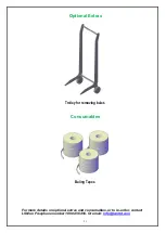
Page 21: ...Optional Extras Trolley for removing bales Consumables Baling Tapes For more details on optional extras and consumables or to re order contact LSM on Freephone number 1890 456 456 Or email info lsmltd com ...

Page 22: ...22 Operating Instructions Reference Decals ...

Page 23: ... tie points on the base pg 24 fig 2 ref pg 22 no 2 4 Place a full size piece of cardboard on to the floor of the baler this will be the base of the bale 5 Close and latch the bottom door B Loading of Baler 1 With the lower door closed and the Top Door open load the material evenly into chamber ref pg 22 no 4 2 When the chamber is fully loaded close and latch the Top Door then press the auto button...

Page 24: ...24 Operating Instructions Diagram fig 1 fig 2 ...

Page 25: ... to the base an extra 300 400mm pg 26 fig 5 pg 22 no 7 3 Un loop the strap from the base Feed the end of the strap that has just been cut through the end with the loop Pull tight and tie off pg 22 no 8 4 Once the bale has been tied Use the strap puller to engage the bale eject bracket pg 27 fig 6 pg 22 no 9 Check the main door is completely open as the bale will not eject unless door is fully open...

Page 26: ...26 fig 5 FINISHED BALE TAPE PULLED OVER BALE AND DOWN TO LOOPS AN EXTRA 300 400MM AND CUT TAPE LOOPED END ...

Page 27: ...the Up Auto buttons on the control panel 3 The centre plate forces the kicker to eject the bale 4 Lower the centre plate for its full stroke by pressing the down button on the control panel after the bale has been removed This will reset the kicker trip into its normal working position 5 Raise the centre plate to the start position by pressing the Up Auto buttons and reset the tapes for the next b...

Page 28: ...et overload Power is on but ram will not move up or down Door is not closed properly The emergency stop Button is pushed in Ensure the door is closed properly NB The Auto Ready light will be illuminated Reset the emergency stop and start again Door is open but can t get the centreplate to rise and eject the bale Push the start Auto buttons together within 0 5 sec Loose Bales Check that all slack w...

Page 29: ...es are performed please ensure that the centre plate is in the fully down position This is for your safety and shall protect you in the event of a hydraulic hose failing The following weekly maintenance is recommended a Oil any door hinges or moving latches with WD40 Grease b Check tightness on all nuts and bolts after the first use and afterwards on a weekly basis If loose contact the LSM Service...

Page 30: ...30 V5HD BALER PARTS LIST ...

Page 31: ... GU 02 001 1 SPOOL HOLDER ASSEMBLY 7 LSM7001Z 1 ELECTRICAL PANEL 8a 250 BD 04 002 3 4 1 KICKER UPRIGHT ASSEMBLY 8b 250 BD 04 001 2 KICKER FOOT 9 350CAN CL 01 000 1 BOTTOM DOOR CLASP 10 350 CP 02 001 1 KICKER TRIP 11 350CAN CP 00 000 1 CENTREPLATE 12 350CAN BDR 00 000 1 BOTTOM DOOR 13 350CAN BDR 02 000 2 TOP DOOR SIDE GUARDS 14 350CAN TDR 00 000 1 TOP DOOR 15a 15b LSM 3159 1 TOP DOOR SWITCH 16a 16b...

Page 32: ...nst the company except that contained in these conditions of sale and the dealer expressly agrees that in accepting delivery he has no recourse in law against the company nor will he join the company as third or other party in any action which results against him for the resale of the company s products 9 WARRANTY The Company warrants its products through the dealer to the first user The Dealer sh...

Page 33: ... and Specifications EN 12100 1 Safety of Machinery Basic concepts general principles for design EN 12100 2 Safety of Machinery Technical Principles and specifications EN 60204 1 Safety of Machinery Electrical equipment of machines EN 574 Safety of Machinery Two handed Control Devices Functional aspects EN 13849 1 Safety of Machinery Safety Related Parts of Control Systems EN 13850 Safety of Machin...

Page 34: ...e use of operational controls Safe loading of machine How to form a bale and tie straps How to safely remove the bale from the machine Machine Safety features Explanation of Machine Safety decals I confirm that all aspects of using the above machine have been explained to my satisfaction Name Print _____________________________________ Name Sign _____________________________________ Position _____...

Page 35: ...working with the machine has been explained to our satisfaction and feel confident in safely operating the machine in the following areas o Safe method of connecting disconnecting power supply o Safe use of operational controls o Safe loading of machine o How to form a bale and tie straps o How to safely remove the bale from the machine o Machine Safety features Name Date Position Trainer Operator...

Page 36: ...36 ...

Page 37: ... working with the machine has been explained to our satisfaction and feel confident in safely operating the machine in the following areas o Safe method of connecting disconnecting power supply o Safe use of operational controls o Safe loading of machine o How to form a bale and tie straps o How to safely remove the bale from the machine o Machine Safety features Name Date Position Trainer Operato...

Page 38: ...38 ...

Page 39: ...39 ELECTRICAL DIAGRAMS ...

Page 40: ...40 ...

Page 41: ...41 ...

Page 42: ...42 ...

Page 43: ...43 Electrical Diagram ...

Page 44: ...ers Wear Plates Positioned Correctly Tight Baler Body Correct taper on body Kicker Functioning correctly returning to proper rest position Kicker Assembly Bolts tightened Kicker Lift Bkt Functioning correctly and bolt tightened Dogs Fitted working correctly Door Clasp Hinges All hinge bolts tight fitted with lock nuts greased where nescessary Top Door Lock Correctly fitted Open close freely Bolts ...

Reviews: