background image

 . . . . . . . . . . . . . . . . . . . . . . . . . . . . . . . . . . . . .  Steps to Check for Problems – Storage Enclosure

630J Storage Enclosure Installation and Overview Guide

4-9

General Behavior of the LEDs

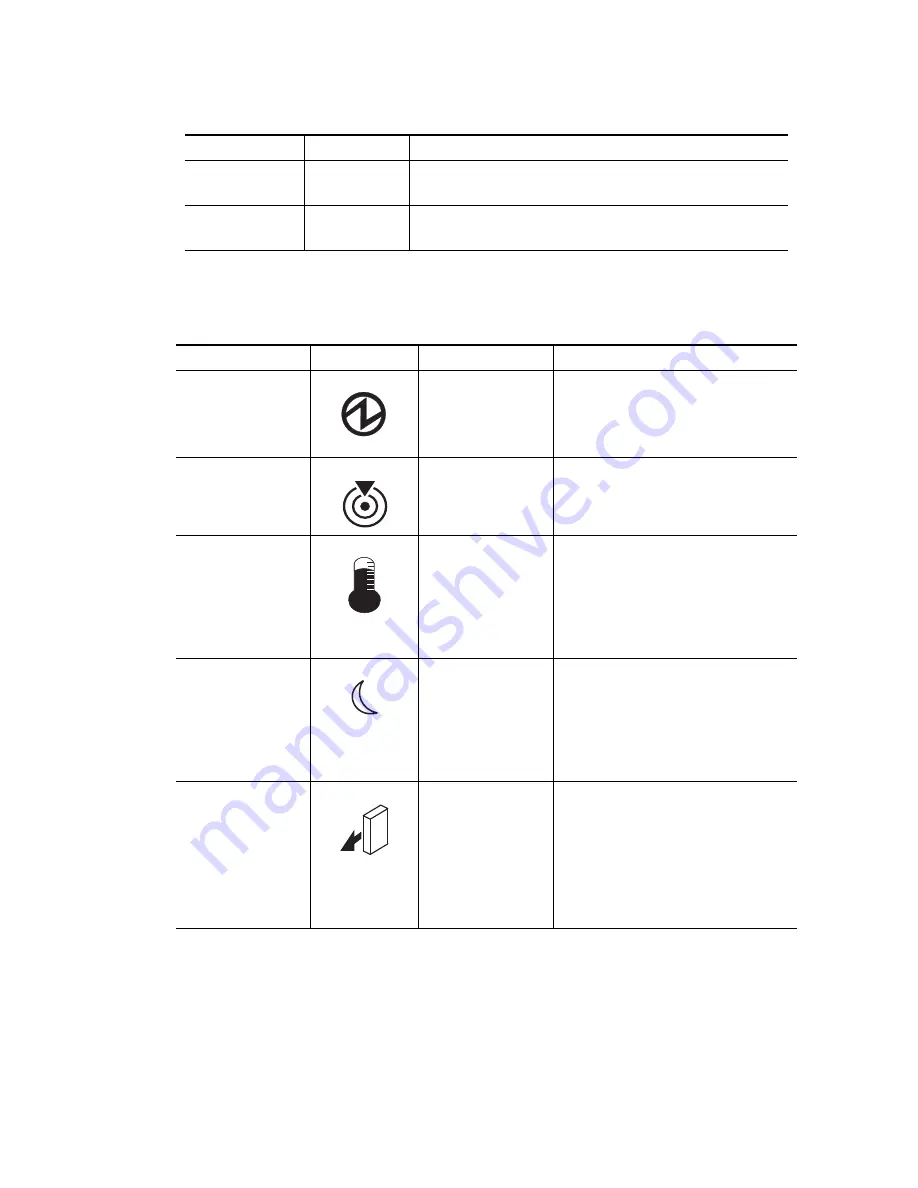
Table 4–7  LED Symbols and General Behavior

H9

A non-catastrophic hardware failure has occurred. The ESM 
is operating in a Degraded state.

J0

Suspended

The ESM canister is incompatible with the storage 
enclosure firmware.

LED

Symbol

Location

General Behavior

Power

Storage enclosure

ESM canister

Power-fan canister

On

 – Power is applied to the storage 

enclosure or the canister.

Off

 – Power is not applied to the 

storage enclosure or the canister.

Locate

Front bezel on the 
storage enclosure

On or blinking

 – Indicates the 

storage enclosure that you are trying 
to find.

Over-Temperature

Front bezel on the 
storage enclosure

On

 – The temperature of the storage 

enclosure has reached an unsafe 
condition.

Off

 – The temperature of the storage 

enclosure is within operational 
range.

Standby Power

Front bezel on the 
storage enclosure

On

 – The storage enclosure is in 

Standby mode, and the main DC 
power is off.

Off

 – The storage enclosure is not in 

Standby mode, and the main DC 
power is on.

Service Action 
Allowed

ESM canister

Power-fan canister

Drive

On

 – It is safe to remove the ESM 

canister, the power-fan canister, or 
the drive.

Off

 – Do not remove the ESM 

canister, the power-fan canister, or 
the drive.

The drive has an LED, but no symbol.

Diagnostic Code

ESM State

Description

Summary of Contents for 630J

Page 1: ...SGI InfiniteStorage IS2224 Installation and Overview Guide 007 5830 001...

Page 2: ...The information in this document supports the SGI InfiniteStorage 2224 IS2224 storage system...

Page 3: ...630J Storage Enclosure Installation and Overview Guide 46277 00 Rev A...

Page 4: ...hs and figures are of equipment prototypes Therefore before using this document consult your LSI representative for information that is applicable and current LSI DOES NOT ASSUME ANY RESPONSIBILITY OR...

Page 5: ...gs to Know General Installation 2 1 Steps to Install Storage Enclosure 2 2 Steps to Install Drives and Drive Canisters 2 10 Things to Know Connecting Power Cords 2 11 Steps to Connect Power Cords 2 12...

Page 6: ...R PROBLEMS Steps to Turn On Power 4 1 Steps to Check for Problems Storage Enclosure 4 2 LEDs on the Storage Enclosure 4 3 ID Diagnostic Codes on the Seven Segment Display 4 8 General Behavior of the L...

Page 7: ...host The number of drives that you are allowed to add to the host Make sure that your storage array supports adding more drives ATTENTION Possible hardware damage To prevent electrostatic discharge d...

Page 8: ...services monitor ESM power supplies and fans A JBOD storage enclosure does not contain RAID controllers Gathering Items Before you start the installation make sure that the hardware items and the sof...

Page 9: ...flashlight Item Included with the Storage Enclosure Power cords The power cords that are shipped with the storage enclosure are for connection to an external power source such as a wall plug Your cabi...

Page 10: ...orage enclosure in the storage array must have a minimum of two drives for proper operation If an enclosure has fewer than two drives a power supply error is reported Figure 1 1 630J Storage Enclosure...

Page 11: ...ltage requirements for both domestic and worldwide operation If you are installing multiple storage enclosures within a cabinet keep as much weight as possible in the bottom half of the cabinet IMPORT...

Page 12: ...re components Steps to Install Storage Enclosure WARNING W08 Risk of bodily injury Two persons are required to safely lift the component WARNING W05 Risk of bodily injury If the bottom half of the cab...

Page 13: ...hat you meet the clearance requirements shown in Figure 2 1 Figure 2 1 Storage Enclosure Airflow and Clearance Requirements 1 76 cm 30 in clearance in front of the cabinet 2 61 cm 24 in clearance behi...

Page 14: ...Enclosure 3 Clearance Above and Below the Existing Enclosure 4 Screws for Securing the Mounting Rail to the Cabinet Front and Rear 5 Industry Standard Cabinet If you are installing the mounting rails...

Page 15: ...for Locking the Mounting Rail Length 3 Mounting Rails 4 Clip for Securing the Rear of the Storage Enclosure b Place the mounting rail inside the cabinet and extend the mounting rail until the flanges...

Page 16: ...rew through the front of the cabinet and screw into the top captured nut in the mounting rail e Insert two M5 12mm screws through the rear of the cabinet and screw into the captured nuts in the rear f...

Page 17: ...anges of the storage enclosure align with the mounting holes on the front of the mounting rails The rear edge of the storage enclosure sheet metal fits into the clip on the mounting rail Figure 2 5 Th...

Page 18: ...w goes through the cabinet rail and engages the bottom captured nut in the mounting rail Tighten the screw b Repeat substep a for the second flange on the other side of the cabinet Figure 2 6 Attachin...

Page 19: ...through them after the left end cap is attached to the storage enclosure Figure 2 7 a Put the top of the end cap on the hinge tab that is part of the storage enclosure mounting flange b Gently press...

Page 20: ...ON Risk of equipment malfunction To avoid exceeding the functional and environmental limits install only drives that have been approved by your supplier System integrators resellers system administrat...

Page 21: ...C power connector on the storage enclosure make sure that you use a separate power source in the cabinet Connecting to independent power sources maintains power redundancy To ensure proper cooling and...

Page 22: ...1 Make sure that the circuit breakers in the cabinet are turned off 2 Make sure that both of the Power switches on the storage enclosures are turned off Figure 2 10 3 Connect the primary power cords f...

Page 23: ...drives in the storage array Navigational Aid Key Terms Page 3 1 Things to Know Connecting the Storage Enclosure to a Host Page 3 2 Things to Know Connecting the Storage Enclosure to Another Storage E...

Page 24: ...On on page 3 4 Things to Know Connecting the Storage Enclosure to Another Storage Enclosure The ESM in each storage enclosure has three SAS connectors Below two of the connectors is an arrow pointing...

Page 25: ...to the connector with the down arrow IMPORTANT Each ESM in the storage enclosure has three SAS connectors Two connectors show an up arrow the other connector shows a down arrow When connecting from an...

Page 26: ...nsferring I O data 3 Stop all I O activity to the storage array 4 Are you adding the storage enclosure to a storage array with existing storage enclosures Yes Go to step 5 No Go to step 8 on page 3 5...

Page 27: ...Configurations You have many options for attaching cables in your storage array configuration Use these basic configurations as a guide to configure your storage array Depending on the number ESMs ho...

Page 28: ...30J Storage Enclosure Installation and Overview Guide Figure 3 1 Simple Configuration Single ESM Single Host and Single Storage Enclosure Figure 3 2 Single ESM Single Host and Multiple Storage Enclosu...

Page 29: ...closure Installation and Overview Guide 3 7 Figure 3 3 Single ESM Dual Host and Multiple Storage Enclosures Figure 3 4 Dual ESMs Dual Hosts and Multiple Storage Enclosures ESM A ESM A ESM A 97009 03 H...

Page 30: ...Connecting the Storage Enclosure to the Host 3 8 630J Storage Enclosure Installation and Overview Guide...

Page 31: ...the storage array 1 Turn off the Power switches on each power fan canister in all of the newly installed storage enclosures 2 Make sure that all of the power cords are connected 3 If the main circuit...

Page 32: ...gure 4 5 LEDs on the Power Fan Canister on page 4 7 The LEDs let you know that your hardware devices are fully operational or whether a fault condition exists 1 Make sure that all of the LEDs show nor...

Page 33: ...tion LED Color On Off 1 Storage Enclosure Locate White Identifiesastorageenclosure that you are trying to find Normal status 2 Service Action Required Amber A component within the storage enclosure ne...

Page 34: ...ity is taking place The power is turned off 2 Drive Service Action Required Amber An error has occurred Normal status 3 Drive Service Action Allowed Blue The drive canister can be removed safely from...

Page 35: ...Tray ID Table 4 4 LEDs on the ESM Canister Location LED Color On Off 1 Host Link 1 Fault Amber At least one PHY of the four connectors is working but another PHY cannot establish the same link to the...

Page 36: ...the four PHYs in the OUT port is working but another PHY cannot establish the same link to the Expansion OUT connector Normal status 8 ESM Expansion Link Active Green At least one of the four PHYs in...

Page 37: ...ower is not available The storage enclosure is not in Standby mode and DC power is available 2 Power Fan DC Power Green DC power from the power fan canister is available DC power from the power fan ca...

Page 38: ...perature condition has been detected in either the ESM or the power supply LL Suspended The midplane SBB VPD EEPROM cannot be accessed Ln Suspended The canister is not valid for this storage enclosure...

Page 39: ...el on the storage enclosure On or blinking Indicates the storage enclosure that you are trying to find Over Temperature Front bezel on the storage enclosure On The temperature of the storage enclosure...

Page 40: ...present DC Power Power fan canister On Regulated DC power from the power canister and the fan canister is present Off Regulated DC power from the power fan canister is not present Link Service Action...

Page 41: ...omes on when it is safe to remove a failed canister If there are data availability dependencies or other conditions that dictate that a canister should not be removed the Service Action Allowed LED st...

Page 42: ...Turning on the Power and Checking for Problems 4 12 630J Storage Enclosure Installation and Overview Guide...

Page 43: ...s after removal from an operating storage enclosure to prevent the possibility of overheating the equipment ATTENTION Possible extended outage You must add the new ESM with the power turned on to ensu...

Page 44: ...return the ESM canister 4 Remove the blank plate that covers the location for the new ESM canister Figure A 1 Figure A 1 Location for the New ESM Canister 1 ESM A Installed 2 Blank Plate 5 Slide the n...

Page 45: ...radio communications Operation of this equipment in a residential area is likely to cause harmful interference in which case the user will be required to correct the interference at his her own expens...

Page 46: ...FCC 2 630J Storage Enclosure Installation and Overview Guide...

Reviews: