background image


System description 


ProtoMat S64/S104 

22/54 


LPKF Laser & Electronics AG | V. 1.0 


Fig. 3: 

Declaration of conformity (English) 


Summary of Contents for S104

Page 1: ...ProtoMat S64 S104 Basic reference to the detailed documentation Order code 10073612 Version 1 0 ...

Page 2: ...kf com Date of issue 13 03 2019 Copyright 2019 LPKF AG This document and its contents in whole and in parts are subject to copyright The reproduction translation or duplication of the contents as photocopy or any digital form requires written permission of LPKF Laser Electronics AG Translation of the German original document ...

Page 3: ...e system product Structure of warning messages and safety notes The safety notes and warning messages in this document identify hazards and risks and they are created in accordance with ANSI Z535 6 2011 and the standards series ISO 3864 The warning messages are structured as follows Warning sign only for injuries Signal word indicating the danger level Type and source of the hazard Consequences of...

Page 4: ...low risk that can cause minor or moderate injury if not avoided Measure to avoid the hazard NOTICE Type and source of the hazard These messages contain information on possible property damage that causes no injury Measure to avoid the hazard Text styles Various text attributes spelling and text structures facilitate reading the document The text attributes highlightings inside this document are de...

Page 5: ... single step Additional information The following symbols are used to indicate additional information This note indicates especially useful information Advanced information This advanced information indicates special knowledge This symbol indicates an intermediate result This symbol indicates a final result Registered Trademarks Product and brand names are trademarks of LPKF Laser Electronics AG r...

Page 6: ...fort to improve our documentation we are asking you to give us your feedback if you notice any discrepancy when working with the system product or if you have any comments or suggestions for improvement At the moment of packaging the system product has been equipped with the latest software version and with the software and hardware documentation currently valid By now new versions of the document...

Page 7: ... 3 Transporting the system 33 4 4 Storage 34 5 First startup 35 5 1 Safety 35 5 2 Requirements of the place of installation 35 5 2 1 Climatic conditions 35 5 2 2 Minimum required space 36 5 2 3 Workplace of the operating personnel 37 5 2 4 Floor 37 5 2 5 The system s center of gravity 38 5 2 6 Connections provided by the customer 38 5 3 Preparations 39 5 4 Connecting the system 39 5 4 1 Connecting...

Page 8: ...toMat S64 and ProtoMat S104 are identically constructed differing only in a few characteristics The following always describes the system For comprehensibility and practicability of the instruction steps it does not matter which of the two systems is described The characteristics that serve for differentiation are marked clearly in this document ...

Page 9: ... is supplied in printed form Documentation Description Basic reference to the detailed documentation Quick guide for first startup Table 1 Overview of the printed documentation The following documentation is supplied on the data medium Documentation Description Basic reference to the detailed documentation Quick guide for first startup User manual ProtoMat S64 S104 Documentation for the ProtoMat S...

Page 10: ...omponents Moving components can cause serious injuries e g crushing injuries or cuts Never grasp moving components when the system is operating Never open any covers when the system is operating Observe the follow up time Before opening the cover ensure that no component is still moving WARNING Risk of injuries by pressurized components Pressurized components e g compressed air supply can move unc...

Page 11: ... bridge or deactivate fuses Always keep moisture away from energized parts because it can cause a short circuit 2 1 3 Thermal hazards CAUTION Burn hazard by hot surfaces During processing some system components can heat up so much that direct contact can cause burns Always wear your personal protective equipment 2 1 4 Hazards by materials or substances WARNING Health hazard by faulty extraction Wh...

Page 12: ...o perform work on electrical systems and to detect and avoid possible dangers on his her own based on his her professional training know how and experience as well as knowledge of the applicable standards and regulations The qualified electrician has been trained for the special field where he she works and knows the relevant standards and regulations Maintenance personnel of the operator Maintena...

Page 13: ...ety risks when working with the system The individual sections of this manual each point out the personal protective equipment PPE that has to be worn during the different tasks of working on the system Description of the personal protective equipment Safety glasses with side shields Safety glasses with side shields serve for eye protection in case of flying debris and liquid splashes Respirator m...

Page 14: ... 8 hours a day 5 days a week The system is intended for use in a laboratory environment Only control the system with the system software that is included in the scope of delivery The system may only be operated with a sufficiently dimensioned extraction system that includes a fine particle filter and active carbon filter LPKF recommends the LPKF extraction system with integrated HEPA filter and ac...

Page 15: ...ser Electronics AG 15 54 Improper use The system must not be used for processing highly combustible materials like e g paper or wood sealed containers hollow parts textiles or food Do not use the system with a different or modified software ...

Page 16: ...quired for your project are predetermined and are picked up and adjusted automatically during processing Isolation distances of 0 2 mm to 0 5 mm are produced using a Universal Cutter smaller isolation distances of 0 1 mm to 0 15 mm using a Micro Cutter Cylindrical tools with diameters of 0 8 mm 3 mm are available for producing wide isolation distances and rub outs The drilling tools of 0 2 mm to 2...

Page 17: ... Unit Power supply 100 240 V 50 60 Hz Nominal power 250 W Stability 10 Mechanical data Data Value Unit Dimensions width x height x depth 680 560 800 26 7 22 31 5 mm in Weight without packaging 95 209 4 kg lbs Weight with packaging 135 297 6 kg lbs Load capacity Data Value Unit Min distributed load 1 75 kN m Min point load on an area of 0 0007068 m 0 0012 kN Pneumatic data Data Value Unit Pressure ...

Page 18: ... Travel speed 150 diagonally 5 9 mm s in s Drilling performance 100 strokes min 1 Collet 1 8 3 175 0 125 mm in Resolution x y 0 47 0 02 µm mil Repeatability 5 0 2 µm mil Accuracy of camera 1 8 0 07 mm pixel mil pixel Emissions Data Value Unit Sound pressure level LpA EN ISO 3744 70 dB A Sound power level LwA EN ISO 3744 70 dB A EMC emission class A Extraction system Data Value Unit Extraction air ...

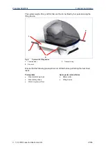
Page 19: ... system and the relevant equipment specify the system model and the serial number on the type label when you contact the LPKF Service Fig 1 Type label S64 S104 Name Description Origin Country of origin Type System type Serial No Serial number Year MFD Year of manufacture Voltage Operating voltage Frequency Line frequency Power Rated power consumption Table 3 Type label S64 S104 ...

Page 20: ...action system ProtoMat S64 S104 and ProConduct PVC soft black 1 Unit for compressed air connection pneumatic tube 6 mm with 1 8 adapter 1 Collet cleaning kit 1 Filter mat 1 Collet wrench 1 Working depth limiter Lubricant special plastic lubrication ISOFLEX Topas 5051 Lubricant Ravenol precision mechanics oil Screwdriver Torx 6 Screwdriver Torx 10 1 Fuse 1 Cleaning device for tools Data medium Docu...

Page 21: ...ProtoMat S64 S104 System description V 1 0 LPKF Laser Electronics AG 21 54 3 4 EC Declaration of conformity Fig 2 Declaration of conformity German ...

Page 22: ...System description ProtoMat S64 S104 22 54 LPKF Laser Electronics AG V 1 0 Fig 3 Declaration of conformity English ...

Page 23: ...n the transport documentation or on the delivery note of the transport company Initiate a complaint 4 2 Packaging The packaging is chosen according to the transport conditions The packaging is to protect the system from transport damage corrosion and other kinds of damage until installation Keep the packaging in its original form Only remove the packaging just before installation Handling packagin...

Page 24: ...p and do not subject it to shocks 4 2 1 Unpacking the system The following describes how to unpack the system Observe also the unpacking instructions WARNING Risk of injury by heavy load The system is heavy and bulky and must not be lifted by one person Incorrect lifting can cause serious injuries e g crushing injuries or spinal injuries Always lift the system with four persons using the enclosed ...

Page 25: ...ersons using the lifting device Fig 4 System with lifting device 1 Foam damper 2 Steel rod 3 Transport sling Ensure that the following prerequisites are fulfilled before performing the described tasks Prerequisites Spare parts and auxiliaries Wear protective gloves Wear safety shoes Work in a group of four Safety cutter Lifting device 2 3 2 1 ...

Page 26: ... Electronics AG V 1 0 Unpacking the system 1 Cut the black polyester straps that secure the transport box using a safety cutter and remove them Fig 5 Polyester straps removed 2 Open the transport box Fig 6 Transport box opened 3 Remove the sheet of cardboard ...

Page 27: ...ProtoMat S64 S104 Transport and storage V 1 0 LPKF Laser Electronics AG 27 54 Fig 7 Removing the sheet of cardboard 4 Remove the two steel rods for lifting the system Fig 8 Removing the steel rods ...

Page 28: ...ectronics AG V 1 0 Fig 9 Steel rods 5 With the help of another person pull the transport box upwards Put the transport box aside Now the padding material at the sides is accessible Fig 10 Padding material 6 Remove the padding material at the sides successively ...

Page 29: ...04 Transport and storage V 1 0 LPKF Laser Electronics AG 29 54 Fig 11 Removing the padding material on the left side Fig 12 Removing the padding material on the right side Now the system is accessible from both sides ...

Page 30: ...Laser Electronics AG V 1 0 Fig 13 System accessible 7 Pull out the four transport slings of the system Fig 14 Transport sling pulled out 8 Push the steel rod through the foam damper and through both of the transport slings on the left side of the system ...

Page 31: ... injury by heavy load The system is heavy and bulky and must not be lifted by only one person Incorrect lifting can cause serious injuries e g crushing injuries or spinal injuries Always lift the system in a group of four using the enclosed lifting device Always wear the recommended safety shoes and protective gloves 10 Lift the system in a group of four with each person holding one end of the rod...

Page 32: ...table and even surface with an appropriate load bearing capacity 12 Remove the steel rods from the transport slings and the foam dampers 13 Lift the front of the system slightly in a group of two 14 Let a third person remove the front transport sling 15 Repeat steps 14 and 15 at the rear of the system for the rear transport sling 16 Save the lifting device for later use The system can be transport...

Page 33: ...ed before performing the described tasks Prerequisites Spare parts and auxiliaries Safety shoes Protective gloves The collet is equipped with a tool Unpacking instructions 1 Switch off the system before transport Ensure that a tool is in the collet or a tool is in the tool magazine before switching off the system 2 Disconnect all connections of the system for an overview of the connections refer t...

Page 34: ...cause serious injuries The lifting device serves only for lifting and putting down the system Transport the system only with a sufficiently load bearing means of transport 3 Move the system on the table trolley to the desired location All connections mentioned above have to be reconnected properly to the system before startup Especially when connecting the extraction hose you have to ensure a secu...

Page 35: ... are laid inappropriately they pose a tripping hazard for the operating personnel Always ensure that the hoses and cables do not pose a tripping hazard NOTICE Property damage by moisture during transport storage When transporting or storing the system moisture can cause damage to the system Ensure that there is no moisture in the system Before first startup of the system wait approx 24 hours to al...

Page 36: ... Value Unit Width 2200 86 6 mm in Depth 1400 55 1 mm in Height 750 29 5 mm in Width 2200 mm 86 6 in Depth 1400 mm 55 1 in Height 750 mm 29 5 in The area marked in red in the following figure is the safety zone It must not be blocked by objects In front of the system at least 400 mm 15 8 in of space should be available for operation and movement Fig 18 Minimum required space 1 Extraction system 2 S...

Page 37: ...on is used for loading and unloading the system PC work station The PC work station is used for monitoring the production and for controlling the system 5 2 4 Floor WARNING Risk of injury by loss of stability Loss of stability due to an improper floor or missing locks can cause uncontrollable movement or tipping of the system This can cause serious injuries Ensure that the floor has a sufficient l...

Page 38: ...2 6 Connections provided by the customer The following connections have to be available for the first startup Electrical data Data Value Unit Power supply 100 240 V 50 60 Hz Nominal power 250 W Stability 10 Pneumatic data Data Value Unit Pressure min 6 bar Standard volume flow 40 l min 6 bar Nl min Compressed air purity acc to ISO 8573 1 2010 04 Data Value Unit Solid particles 5 Class Water 4 Clas...

Page 39: ...nstallation Provide the connection materials hoses tubes cables etc The room has to be clean and almost dust free 5 4 Connecting the system Once all preparations are concluded the system is connected in the following order Connecting the extraction system Connecting the compressed air supply Establishing a connection between the camera and the PC USB port Establishing a connection between the syst...

Page 40: ...urer Use only sockets with protective earth conductor for connecting Do not use extension cables Do not bend the extraction hose Do not block the air flow 5 4 1 Connecting the extraction system The extraction system is an optional accessory that can be ordered at LPKF The following describes the required steps for connecting the JetStream iSeries AX079 25 Material The following material is require...

Page 41: ... operating personnel Always ensure that the hoses and cables do not pose a tripping hazard 1 Connect the provided nozzle to the extraction hose 2 Connect the end of the extraction hose that is now equipped with the nozzle to the extraction tube of the system Fig 26 Extraction hose connected to the system 3 Connect the other end of the extraction hose with the extraction system Fig 27 Connecting th...

Page 42: ...nnecting the control cable 6 Connect the extraction system to the mains power supply Fig 30 Connecting the mains cable The extraction system has been connected LPKF recommends to set the extraction system to 70 You can adapt the run down time of the extraction system according to your requirements For further information refer to the user manual of the extraction system ...

Page 43: ... Tripping hazard by hoses and cables Hoses and cables are routed to the system If the hoses and cables are laid inappropriately they pose a tripping hazard for the operating personnel Always ensure that the hoses and cables do not pose a tripping hazard 1 Connect the pneumatic tube to the compressed air connector G 1 4 Fig 32 Connecting the pneumatic tube to the system 2 Connect the pneumatic tube...

Page 44: ...e camera to the PC CAUTION Tripping hazard by hoses and cables Hoses and cables are routed to the system If the hoses and cables are laid inappropriately they pose a tripping hazard for the operating personnel Always ensure that the hoses and cables do not pose a tripping hazard 1 Connect the B cable of the provided USB cable to the slot of the system 2 Connect the A cable of the provided USB cabl...

Page 45: ...d cables Hoses and cables are routed to the system If the hoses and cables are laid inappropriately they pose a tripping hazard for the operating personnel Always ensure that the hoses and cables do not pose a tripping hazard 1 Connect the B cable of the provided USB cable to the slot of the system Fig 36 Connecting the USB cable to the system 2 Connect the A cable of the provided USB cable to the...

Page 46: ...First startup ProtoMat S64 S104 46 54 LPKF Laser Electronics AG V 1 0 Fig 37 Connecting the USB cable to the PC The USB cable has been connected ...

Page 47: ...ing the mains cable CAUTION Tripping hazard by hoses and cables Hoses and cables are routed to the system If the hoses and cables are laid inappropriately they pose a tripping hazard for the operating personnel Always ensure that the hoses and cables do not pose a tripping hazard 1 Connect the mains cable to the system 2 Connect the mains cable to the earthed wall socket Ensure that the earthed wa...

Page 48: ...s and cables are laid inappropriately they pose a tripping hazard for the operating personnel Always ensure that the hoses and cables do not pose a tripping hazard 1 Connect the mains cable to the PC 2 Connect the mains cable to the earthed wall socket The mains cable has been connected 5 4 7 Dummy tool The system is equipped with a dummy tool for transport It is in the collet and must not be remo...

Page 49: ...ng system requirements have to be met in order to install CircuitPro PM successfully Component Minimum system requirements CPU 2 GHz LPKF discourages the use of the following CPU because it causes problems Intel Xeon RAM 2 GB Memory requirements 2 GB Graphics board With 128 MB dedicated memory non shared memory LPKF discourages the use of the following graphics boards because they cause problems I...

Page 50: ...0 PCs with Intel Core i3 i5 or i7 processor of the 6th generation Skylake do not fully support the USB 2 0 interface of the installed camera If problems arise while transmitting the camera image LPKF recommends to use a USB 3 0 camera 5 6 Reading the user manual 1 2 3 4 ...

Page 51: ... space 36 Fig 19 Workplace of the operating personnel 37 Fig 20 Center of gravity of the system 38 Fig 21 Connecting the system 39 Fig 22 Extraction hose 40 Fig 23 Nozzle for extraction hose 40 Fig 24 Mains cable 40 Fig 25 Control cable 40 Fig 26 Extraction hose connected to the system 41 Fig 27 Connecting the extraction hose 41 Fig 28 Control cable 42 Fig 29 Connecting the control cable 42 Fig 30...

Page 52: ...14 mechanical data 17 O operating personnel 13 P packaging symbols on the packaging 24 unpacking the system 24 pneumatic data 17 38 process data 18 processing procedures 14 protective gloves 13 Q qualified electrician 12 R requirements of the place of installation 35 climatic conditions 35 connections provided by the customer 38 floor 37 minimum required space 36 the system s center of gravity 38 ...

Page 53: ......

Page 54: ......

Reviews: