


LP Morgan Installation Instructions | 13
LP Morgan Flipper Manual
We supply these units pre-programmed to operate via a maintained SPST
switch (a single throw relay). The supplied switch should be connected to the
“Up” and “Common” terminals ONLY.
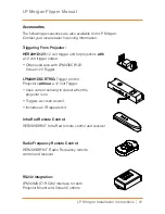
Should you wish to use a different sort of switching method (eg. SPDT), you
can easily program the device to do so. However, you will need a receiver
eye and special programming remote (available as our Installer’s Kit -
LPM43INSKIT)
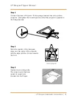
Use a small flat
screwdriver to prise
open the motor and
mains terminals
Wiring Diagram
12V Positive
12V Negative
Motor Blue
Motor Brown
AUX
JACK
EYE
JACK
Switch Common
Switch Up
Switch Down
(Not used
in standard
configuration)
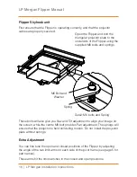
These control units have an in-built stall sensor which is a necessary feature if
you are installing a Flipper into a tabletop.
To activate the stall feature you need to purchase a programmer’s kit
(LPM43INSKIT) has included detailed instructions on setting a calibrating the
current threshold.
Contact Herma if you want further information on stall settings.
Stall Sensing