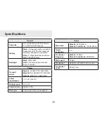
background image

29

Limited Warranty 

Subject to the terms, conditions and limitations set forth in the Navico 

Limited Warranty (hereinafter, the “Warranty”), Navico warrants that its 

products, when properly used and ins stalled will be free from defects in 

material and workmanship for a period of:

Lowrance, Eagle & Northstar Explorer, excluding Lowrance HDS: Twelve 

(12) months

Peripheral devices for all Navico brands including, but not limited to, trans-

ducers, fuel and wind sensors, cables: Twelve (12) months

Northstar (excluding Explorer), Simrad, B&G, Lowrance HDS systems and 

Yellow Ethernet connected products, excluding all peripheral devices for all 

brands: Twenty-four (24) months

from the date of first purchase (the “Warranty Period”).

For the purpose of this Warranty, “date of first purchase” means the date that 

the product was purchased by the first retail customer; or in the case of a 

product installed on a new vessel by a Certified/Approved Navico Boatbuild-

er, the date that such vessel was purchased by the first retail customer.

Navico will, at its sole discretion, repair or replace with new or refurbished 

parts or product, or equivalent product, any proven defective products or 

components returned to Navico, or its approved agent during the Warranty 

Period  in  accordance  with  the  terms,  conditions  and  limitations  set  forth 

below.

Such repairs or replacement will be the sole remedy of the customer under 

this Warranty Repaired or replaced product will be warranted for the balance 

of the original product’s Warranty Period.

Standard Warranty Service

To obtain your remedy under this Warranty:

1.   Contact Navico or your local Navico Certified/Approved dealer or Dis-

tributor  to  confirm  your  product’s  warranty  status  and  obtain  a  Return 

Material Authorization number.  A list of Navico Certified/Approved deal-

ers is available at www.navico.com or through your original Navico dealer 

of purchase.

2.   Upon authorization securely pack the product, along with a valid proof 

of purchase (indicating the product purchased, serial number, place and 

date of first purchase), and any other information Navico requests, such 

as a copy of any Return Material Authorization form you may receive.  

Ship the product and other required items to the address specified by the 

Navico Certified/Approved dealer contacted.

You must pay for shipping and any insurance to get the product to the Navi-

co Service Centre.  You assume all risk of loss and/or damage to the product 

until it arrives at the Navico Service Centre.  Navico will pay for shipping 

of the returned product to your nominated address, within the jurisdiction 

of first purchase.  Shipping mode and carrier is at Navico’s discretion; the 

customer must request, and pay for, any variation.

Navico will not be responsible for the loss of or alteration of any user data 

and settings stored in the product.  You should back up or otherwise pre-

serve all data before sending the product to Navico.

Limitations and Exclusions

In addition to other limitations and exclusions set forth herein, Navico is not 

responsible for, and this Warranty does not cover:

•   products  where  the  serial  number  has  been  altered,  mutilated  or  re-

moved;

•   failures due to abuse, misuse, overvoltage, accident, unauthorized altera-

tion or repair, improper installation (whether or not by a Navico Certified/

Approved dealer or service agent), shipping damage, alterations, corro-

sion and normal wear and tear;

•   costs  associated  with  routine  system  checkouts,  calibration,  alignment, 

sea-trials or commissioning;

Summary of Contents for Mark 5X DSI

Page 1: ...Mark 5x Mark 5x Pro Elite 5x sonar Installation Operation manual...

Page 2: ...cial distribution of this manual is strictly prohibited Navico may find it necessary to change or end our policies regulations and special offers at any time We reserve the right to do so without noti...

Page 3: ...ishing Mode 17 Restoring Defaults 18 Standby mode 18 Advanced Mode 18 Sonar Operation 19 Viewing Sonar History 19 Sensitivity 20 Auto Sensitivity 20 Depth Range 21 Frequency 21 Sonar Options menu 21 O...

Page 4: ...l bit Marine grade epoxy Shoot thru hull install only 29 0 136 3mm drill bit Zip ties trolling motor mount Phillips Slotted head screwdriver TMB S bracket kit Skimmer trolling motor mount NOTE Make su...

Page 5: ...lose bottom signal when the boat is on plane Install transducer at least 1 3m away from the engine s lower unit B Aligning Ratchets on Transducer bracket You will use the ratchets to ensure the transd...

Page 6: ...ed with the dot stamped in the bracket Reassemble the transducer and bracket and place it against the transom Check to see if the transducer will adjust so its face is parallel with the ground 5 Repea...

Page 7: ...the 10 screws Routing cables When mounting your transducer make sure to leave some slack in the cable near the transducer If you need to drill a hole in the transom to pass the connector through the h...

Page 8: ...flotation material sandwiched within the hull consult the boat manufacturer In a shoot thru hull installation the transducer is epoxied to the inside of the boat hull A transducer can not shoot throu...

Page 9: ...oil or grease The surface of the hull must be flat so the entire transducer face is in contact with the hull Also make sure the cable is long enough to reach the sonar unit To use shoot thru hull ins...

Page 10: ...ere are no air pockets in the epoxy layers Stop pressing when it bottoms out on the hull 5 Apply pressure to hold the transducer in place while the epoxy sets Be careful not to move the transducer whi...

Page 11: ...ing motor It only needs a hose clamp adjustable strap Installing transducer on trolling motor Using the components supplied with the TMB S bracket attach the skimmer 1 transducer to the bracket as sho...

Page 12: ...bstruct the display unit when it is installed on the bracket To install bracket mount Place the bracket on the desired mounting surface and mark the four mount 1 ing holes If you want to run the unit...

Page 13: ...g surface and then pull them through the cabling hole in the center of the bracket Align the mounting bracket with the four mounting holes and use the supplied 4 screws to fasten it to the mounting su...

Page 14: ...the fuse to the positive terminal on the battery Use 18 gauge wire to extend the power or ground wires Connect the Power cable to the 3 Power port on the back of the dis play unit 12V Optional paddle...

Page 15: ...view KEYPAD controls cursor selects items on menus MENU Opens settings context and page menus ENTER finalizes menu selections LIGHT POWER controls backlight level and turns unit on off Basic Operatio...

Page 16: ...press Enter Pages This unit has four page screens Sonar Split Zoom Split Frequency and Split Flasher Sonar Displays the water column moving from right to left on your unit s screen Split Zoom Display...

Page 17: ...15 Accessing Settings menu Selecting Menu items Accessing Pages Accessing Sonar menu Sonar menu Settings menu Basic Operation Settings menu Sonar settings menu...

Page 18: ...ress enter Basic Operation Switches keyboard between Alpha and Qwerty layout Switches letters to uppercase lowercase Working with menus Scrollbars Select the scrollbar and press the keypad left decrea...

Page 19: ...ter Bottom brown white background 50 ping speed Brackish Water Bottom brown blue background higher ASP slightly lower chart speed Basic Operation Exiting menus If a screen or menu has an exit option C...

Page 20: ...te Enables manual control of ping rate Alarms Enables Arrival Off Course and Anchor alarms Units Enables units for Distance Speed Depth Temperature and Bearings Restoring Defaults Resets unit options...

Page 21: ...ry and making adjustments to the sonar menu Viewing Sonar History Mark 5X Pro Elite 5x only You can review your sonar history by pressing the keypad to the left until the screen starts to move in reve...

Page 22: ...on Sensitivity set to 65 percent Sensitivity set to 85 percent Colorline Advanced mode only Separates strong sonar echoes from weak sonar echoes That makes it easier to distinguish fish or structure f...

Page 23: ...changes to sensitivity with Auto Sensitivity turned on You will have to turn it off to make significant adjustments surface Upper and lower limits must be at least 6 5 feet 2m apart Frequency Mark 5x...

Page 24: ...y using palettes with varying degrees of color and brightness Amplitude Scope Allows you to see the amplitude of real time echoes before they appear on the display Fish ID Displays fish echoes as fish...

Page 25: ...oved or removed from the display from the Overlay data menu Press Menu from the Overlay Data screen to make adjustments to overlay data Overlay Data Used to display selected data on the Sonar screen T...

Page 26: ...udio and advanced mode Language Selects the language used on menus and text boxes About Displays software information about this unit Settings menu Sonar Settings System Settings Alarms Simulator Adva...

Page 27: ...the receiver near the surface Manual Mode In this mode the unit sends sonar signals only to the depth range you select instead of automatically searching for the bottom That makes it easier to focus o...

Page 28: ...eel Transducer Keel Offset 3 5 feet Beforesettingkeeloffset measurethedistance from the transducer to the lowest part of the keel If the keel is 3 5 feet below the transducer it will be input as 3 5 f...

Page 29: ...e selected Shal low alarm threshold Fish alarm sounds a tone when a fish symbol appears on the dis play Fish alarm will only work with Fish ID turned on Units Allows you to select the unit of measure...

Page 30: ...els Power Transmit power Mark 5x 1600W PTP 200W RMS Mark 5x Pro 2400W PTP 300 RMS Elite 5x 4000 PTP 500W RMS Power requirement 10 to 18 Volts DC Voltage input 10 to 17V Current drain Typical 25A Fuse...

Page 31: ...r or Dis tributor to confirm your product s warranty status and obtain a Return Material Authorization number A list of Navico Certified Approved deal ers is available at www navico com or through you...

Page 32: ...Y OTHER COUNTRY OR JURISDICTION This product will not function or perform as intended and will not be of merchantable satisfactory or acceptable quality if sold distributed transported or used outside...

Page 33: ...otors check one 1 2 3 4 Engine Horsepower check one 9 15 16 25 26 50 51 75 76 125 126 175 176 225 226 250 250 Gas Motor Type check one Outboard Inboard Sterndrive Jetdrive Other Boat Length feet 17 17...

Page 34: ...32...

Page 35: ...the dealer in the country where you purchased your unit Accessory Ordering Information LEI Extras Inc is the accessory source for sonar and GPS products manufactured by Lowrance Electronics To order...

Page 36: ...Visit our website www lowrance com Copyright 2009 All Rights Reserved Navico Holding AS 988 0180 00a...

Reviews:

Related manuals for Mark 5X DSI