background image

13

select “Auto Sensitivity” and press the ENT key. To turn it off, repeat the
above steps. Press the EXIT key to erase the menu.

COLORLINE
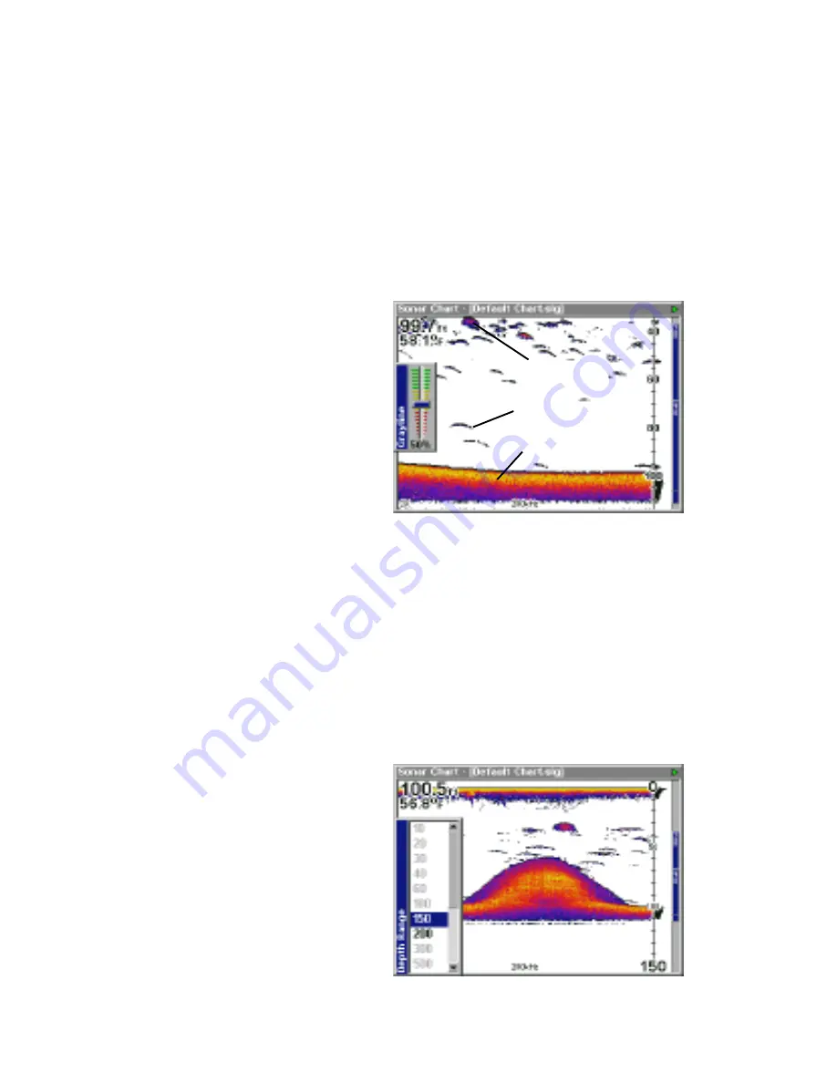
Colorline lets you distinguish between strong and weak echoes. It “paints”
gray on targets that are stronger than a preset value. This allows you to
tell the difference between a hard and soft bottom. For example, a soft,
muddy or weedy bottom returns a weaker signal which is shown with a
narrow, lighter colored colorline. A hard bottom returns a strong signal
which causes a wide gray line.

If you have two signals of equal
size, one with color and the other
without, then the target with color
is the stronger signal. This helps
distinguish weeds from trees on
the bottom, or fish from structure.

Colorline is adjustable. Since
Colorline shows the difference
between strong and weak sig-
nals, adjusting the sensitivity may
require a different Colorline level, also. The level chosen by the unit at
power on is usually adequate for most conditions. Experiment with your
unit to find the Colorline setting that’s best for you.

To adjust the Colorline level, press the MENU key, then select “Colorline”.
The screen above appears. Use the up or down arrow keys to adjust the
color level. You can see the change on the chart record as you press the
keys. After you’ve finished, press the EXIT key to erase the menu.

RANGE - Automatic
When turned on for the first time,
the bottom signal is  automatically
placed in the lower half of the
screen. This is called Auto Rang-
ing and is part of the automatic
function. However, depending
upon the bottom depth and the
current range, you can change
the range to a different depth. To
do this, press the MENU key, then
select “Depth Range”. The screen
at right appears. Press the up or down arrow keys to select a different

STRONG SIGNAL

WEAKER SIGNAL

COLORLINE

Summary of Contents for LCX-15 CI

Page 1: ...75 INSTALLATION AND OPERATION INSTRUCTIONS LCX 15CI and LCX 15CT TM WWW LOWRANCE COM TM ...

Page 2: ...ertain a clear safe path to the waypoint is always available The operating and storage temperature for your unit is from 4 degrees to 167 degrees Fahrenheit 20 to 75 degrees Celsius Extended storage temperatures higher or lower than specified will cause the liquid crystal display to fail Neither this type of failure nor its consequences are cov ered by the warranty For more information consult the...

Page 3: ... not oc cur in a particular installation If this equipment does cause harmful inter ference to radio or television reception which can be determined by turn ing the equipment off and on the user is encouraged to try to correct the interference by one or more of the following measures Reorient or relocate the receiving antenna Increase the separation between the equipment and receiver Connect the e...

Page 4: ...ormation 63 Datum List 64 Database License Agreement 67 Database Limited Warranty 68 Saving and Replaying a Sonar Record 69 Transferring GPS Data to from a MMC 70 INTRODUCTION 1 ACCESSORIES 1 TRANSDUCERS 1 INSTALLATION 2 Mounting 2 Power Connections 3 NMEA DGPS Wiring 4 Accessory Connections 5 Speed Temperature Sensor 5 MMC 7 KEYBOARD 8 SONAR OPERATION 9 Pages 9 Full Sonar Chart 9 Split Zoom Chart...

Page 5: ...ransducers is shown below ACCESSORIES Model Part Gimbal Knobs GK 9 101 80 Gimbal Bracket GB 12 101 78 Power Cable PC 21X 99 56 Protective Cover CVR 1 101 82 Sun Shade SS 1 101 83 MMC Drawer MMCD 1 101 84 MMC Interface MMCI 101 85 Cigarette Adapter Cable CA 4 99 59 Power Connector Repair Kit TC 4X 101 86 MMC Card 8MB MMC 8 101 87 MMC Card 16MB MMC 16 101 88 Transducer Extension Cable 12 XT 12 99 57...

Page 6: ... bracket base allow wood screw or through bolt mounting Make certain there is enough room behind the unit to attach the power and other cables Once the best location is determined use the bracket as a template and mark the mounting holes and the hole for the cables Drill a 1 0 hole for the cables Screw the bracket to the mounting surface IMPORTANT In order to pass all connectors through the 1 hole...

Page 7: ...r and ground wires the other is for the NMEA DGPS interface See below for NMEA DGPS wiring instructions The power cable has two wires red and black The black wire connects to the battery s negative termi nal The red wire is the positive wire Connect it to the fuse holder supplied with the unit Connect the other end of the fuse holder to the positive side of the battery Make certain to attach the f...

Page 8: ... receivers These in turn connect to the GPS receiver such as the LCX 15CI 15CT with the LGC 12S GPS mod ule This gives more accurate positions than is otherwise possible NMEA DGPS Wiring The LCX 15CI 15CT has two NMEA 0183 version 2 0 ports Com port one can be used for either NMEA or DGPS Com port two is for NMEA output only Comunications port one uses the yellow wire wire for transmit the orange ...

Page 9: ...sensor in addition to up to three temperature sensors All transom mount Skimmer transducers have a temperature sensor built into them To add another temperature sensor besides the one in the transducer requires a MY 4X Y adapter cable and a TS 2X temperature sensor The transducer plugs into one end of the MY 4X the TS 2X tem perature sensor plugs into another and the last end plugs into the SO NAR...

Page 10: ...with Speed Temp Sensor Temperature Sensor Speed Temp Sensor X 15CI 15CT Sonar Connector Temperature and Speed Temperature Installation Examples To Transducer To Transducer To Additional Temp or Speed Sensors if needed To Additional Temp Sensors if needed ...

Page 11: ...the MMC cartridge FACE DOWN see above Slide the drawer back into the unit and twist the retainer clockwise The MMC is now ready for use For more information on saving and recalling sonar data to the MMC see page 68 Map storage requires the MapCreate software and a MMC Interface If your unit did not come with these they are available for purchase sepa rately You can also store plot trails icons way...

Page 12: ...ey switches the unit between dif ferent sonar or GPS modes WPT Saves and recalls waypoints MENU Press this key to show the menus and gain access to most functions EXIT Clears menus and entries ENT ICONS Used to select entries and accept menu selections When a menu is not showing pressing this key activates the ICON menu PWR LIGHT Turns the unit on and off When the unit is on pressing this key turn...

Page 13: ...rst time or when it s reset to the factory defaults The bottom sig nal scrolls across the screen from right to left Depth scales on the right side of the screen aid in de termining the depth of targets The line at the top of the screen represents the surface The bot tom depth and surface tempera ture if equipped with a temperature sensor show at the top left corner of the screen The FasTrak displa...

Page 14: ...n the left side of the screen and data from the 200 kHz transducer element on the right All features are the same as the Full Sonar Chart Digital Chart This mode shows the chart on the right side of the screen The left side has seven large digital boxes containing the Water Depth at the top of the screen with the shal low and deep alarm settings im mediately beneath the depth Water Speed from an o...

Page 15: ...hrough its functions and features To use the menus press the MENU key Note There are two layers of menus Pressing the MENU key once brings up the first set of menus pressing the menu key again brings up the second set Use the arrow keys to navigate through the menus Generally to make a selection from a menu highlight the desired item with the arrow keys then press the ENT enter key The EXIT key er...

Page 16: ...the same whether the unit is in the automatic or manual mode To adjust the sensitivity press the MENU key then select Sensitiv ity The screen at right appears The sensitivity control has a ver tical adjustment bar The number at the bottom of the bar shows the percentage of sensitivity in use To increase the sensitivity level press the up arrow key As you press the key the control knob will move up...

Page 17: ...g and weak sig nals adjusting the sensitivity may require a different Colorline level also The level chosen by the unit at power on is usually adequate for most conditions Experiment with your unit to find the Colorline setting that s best for you To adjust the Colorline level press the MENU key then select Colorline The screen above appears Use the up or down arrow keys to adjust the color level ...

Page 18: ...limit feature This lets you pick the shallow and deep range limits that are shown on the screen provided there is at least ten feet between the upper and lower limit For example a range from 12 feet to 34 feet To change the upper and lower limits press the MENU key then select Upper and Lower Limits A screen similar to the one at right appears Upper Limit is high lighted To select it press the ENT...

Page 19: ...and bottom of the 2X zoom bar Pressing the key again will give a 4X zoom and only the echoes between the top and bottom of the 4X bar will show on the screen Press the ZOUT key to return the display to the normal mode STOP CHART To temporarily stop the chart from scrolling press the MENU key then select Stop Chart from the menu and press the ENT key Repeat these steps to start the chart again CHAR...

Page 20: ...s the MENU key select Chart Data Shown and press the ENT key A screen similar to the one at right appears The unit can show the digital depth in large numbers default small numbers or off To change it se lect the Depth label then press the ENT key Highlight the desired set ting using the arrow keys then press the ENT key To change any of the other settings on this screen select them using the arro...

Page 21: ...three levels of surface clarity available low medium or high It can also be turned off The default level is low To change it highlight Surface Clarity on the Sonar Features menu then press the ENT key to select it Use the cursor keys to highlight the desired level of surface clarity then press the ENT key Noise Rejection The automatic noise rejection system built into this unit constantly evalu at...

Page 22: ...rds from a group of limbs is the hardest object for the Fish Symbols feature to distinguish from fish You may see Fish Symbols symbols on the screen when actually there are no fish Practice with the unit in both the Fish Symbols mode and without to become more familiar with the Fish Symbols feature The default for Fish Symbols is off To turn the Fish Symbols feature on highlight Fish Symbols on th...

Page 23: ...reen at the top of the page and press the ENT key The screen at right appears Contrast is highlighted on this menu by default To adjust it press the ENT key and use the left or right arrow keys to change it Press the ENT key when fin ished To adjust the backlighting s brightness first turn it on by pressing the PWR key Next highlight the Backlight label then use the arrow keys to adjust it Press t...

Page 24: ...ayed when an alarm is triggered Select Alarm Style then press the ENT key Choose the desired setting then press the ENT key again The setting is saved and will be played the next time an alarm sounds ALARMS This unit has three different types of sonar alarms The first is the Fish Alarm It sounds when the Fish I D feature determines an echo or group of echoes is a fish Another alarm is the Zone Ala...

Page 25: ...ghlight the Depth label then press the ENT key The screen shown at right appears Use the up or down arrow keys to select the number the right and left keys to move from number to number in the depth For example to set the shallow alarm depth to 10 feet press the right arrow key until the next to last number is highlighted then press the up arrow key once The changes the second 0 to a 1 Next press ...

Page 26: ... detected by the Fish I D feature A different tone sounds for each fish symbol size shown on the display To turn the fish alarm on select Fish Alarm from the sonar alarms menu and press the ENT key Repeat the above steps to turn the fish alarm off SONAR SETUP The Sonar Setup menu lets you select the transducer type set the keel offset calibrate the water speed sensor reset the trip dis tance and t...

Page 27: ...diately adds one foot to the digital depth display at the top of the screen The adjustment menu automatically erases when the ENT key is pressed Note Another way to use the keel offset feature is if you want to know the depth of the water below the lowest part of the boat instead of the sur face To do this measure the lowest part of the boat below the transducer In this example we ll use 3 feet No...

Page 28: ...at right ap pears Turn the simulator on by highlight ing Simulator On and pressing the ENT key The simulator im mediately begins operation If you have a MMC installed you can select previously saved charts to show instead of the standard one Select the chart from the Charts Used menu The unit will use the se lected chart When you are finished with the settings on this screen press the EXIT key to ...

Page 29: ...s the ENT key to change it Once you have each field set the way you want press the EXIT key to erase the menu Communications Ports This unit has two serial ports Each can be set to send NMEA data or receive data from a DGPS receiver The baud rate is adjustable from 1200 to 115200 baud The default is 9600 To change a setting on this screen highlight it using the cur sor keys then press the ENT key ...

Page 30: ... in the same manner If you re using a Starlink DGPS receiver leave the Starlink Auto Tuning Mode checked If not deselect this box Press the EXIT key when you re finished with this menu Configure NMEA You can configure the unit to use specific NMEA sentences Select Configure NMEA and press the ENT key The menu at right ap pears showing the prefix of the available NMEA sentences A check mark next to...

Page 31: ...ersion number of the operating system select Software Information from the System Setup menu A screen appears with the system information Press the EXIT key to erase this screen SUN MOON CALCULATOR This unit has a sunrise sunset and moonrise moonset calculator that shows this information any where and anytime in the world To use it press the MENU key twice then select Sun Moon Calculator The scree...

Page 32: ... path to a waypoint It provides navigation data to the waypoint regardless of obstructions Therefore the prudent navigator will not only take advantage of all available navigation tools when travelling to a waypoint but will also visually check to make certain a clear safe path to the waypoint is always available INTRODUCTION TO GPS The Global Positioning System GPS was developed by the United Sta...

Page 33: ...any manufacturers including Lowrance sell a DGPS receiver that attaches to your GPS receiver The DGPS sys tem transmits correction signals that increase the accuracy to about 10 meters The DGPS receiver takes signals from these land based trans mitters and gives them to the GPS receiver which then uses them to show a more accurate position You can use the signals from all of the Coast Guard DGPS s...

Page 34: ...ches to Auto Search The receiver looks for any satellite in the sky Due to ad vanced technology the auto search time has shrunk to about five min utes so the longest time you should ever have to wait is ten minutes from the time you turn the unit on until it locks onto the satellites and shows a position Once the unit locks onto the satellites it should take less than a minute to find your positio...

Page 35: ...tion time and date thereby giving it the data it needs to determine which satellites are in view Once the satellites are known the receiver searches for only those satellites making a lock faster than an auto search method All position and navigation data flashes until the unit acquires a position Do not rely on any data that is flashing When the numbers are flashing they represent the last known ...

Page 36: ...press the PAGES key A menu similar to the one at right appears Press the left or right arrow key to highlight the Status Navigation or Map label The Map menu gives you five se lections Full Map Digital Data Two Position Formats Two Maps or Map with Sonar split screen map and sonar Once the desired menu is selected press the EXIT key to erase the menus Status This screen shows a graphical view of t...

Page 37: ...stomizing the Status Screen Many of the digital displays can be customized to show different digital data than the defaults To customize this screen press the MENU key while the Status screen is showing Scroll down to the bottom of this menu to the Customize label and select it The Position Error bar flashes signi fying that the window can be changed Press the MENU key to show a menu of available ...

Page 38: ...sent posi tion symbol touches the right cross track error line then you are 20 mile to the right of the desired course You need to steer left to return to the desired course You can use the ZIN or ZOUT keys to change the cross track error range A circle depict ing your destination waypoint appears on the screen as you approach the waypoint as shown on the screen at right Travel Time is the time th...

Page 39: ...t have to navigate to a waypoint however to use the map Using the map is as simple as pressing the PAGES key then Full Map A screen similar to the one at right appears The arrow flashing in the center of the screen is your present position It points in the direction you re travelling The solid line extend ing from the arrow is your plot trail or path you ve taken The plotter s range shows in the l...

Page 40: ...de while seeing a much larger area on the other Press the PAGES key then an arrow key to select the right or left map Map With Sonar shows the map on the left side of the screen and the sonar on the right The Z IN and Z OUT keys zoom in and out all maps to enlarge or reduce their coverage area The available ranges are 0 1 0 15 0 2 0 3 0 4 0 6 0 8 1 1 5 2 3 4 5 6 8 10 15 20 30 40 60 80 100 150 200 ...

Page 41: ...he ENT key was pressed to the cursor s present location The distance and bearing to the second location show in a box next to the cursor s crosshairs To mea sure another two points simply move the cursor and press the ENT key Press the EXIT key to erase the cursor The unit centers your present position on the screen after erasing the cursor Map Orientation By default this receiver shows the map wi...

Page 42: ...iew the present position moves straight towards the top of the display Remem ber in the track up mode the screen rotates as you change di rection It always keeps your di rection of travel track heading towards the top of the screen NORTH UP TRACK UP COURSE UP In the course up mode the screen is locked into your origi nal bearing to the recalled waypoint regardless of your track To select the desir...

Page 43: ...te it Press the EXIT key to erase the menus Repeat these steps to turn it off Range Rings Grid Lines The map screen can be custom ized with rings that are 1 2 of the range and or grids that divide the plotter into equal segments of lati tude and longitude To do this press the MENU key then high light the desired option then press the ENT arrow key to turn it on Press the EXIT key to erase the menu...

Page 44: ...can be used to mark fishing or hunting loca tions landmarks boat ramps and virtually any point of interest An icon can be placed at your present position or at the cursor s location To place an icon at your present position simply press the ENT key while a mapping screen is on The screen shown at right ap pears Use the arrow keys to highlight the desired icon Now press the ENT key again The mappin...

Page 45: ...ase from memory then press the ENT key The unit returns to the map screen with all of the selected icons erased You can delete individual icons by selecting Delete From Map Once this menu is selected the unit returns to the mapping screen with the cursor activated as shown at right Use the arrow keys to move the cursor to the icon that you want to erase Once the crosshairs are on top of the icon p...

Page 46: ...ail s name and number of points used can be changed by selecting them with the arrow keys and the ENT key If the Active box is selected then the points are updated on this trail If Visible is selected then the trail shows on the map Select Delete Trail to erase the trail and its settings Navigate a Trail You can follow a saved trail by using the Navigate feature on the Edit Trail menu shown above ...

Page 47: ...ck to the boat ramp using the plot trail press the Menu key twice select My Trails then select the desired plot trail and click on the Naviate button The screen shown a the bottom of the previous page appears Point 1 on the list is the boat ramp Click on the Reverse button to reverse the plot trail as shown at right Now the last point on the plot trail 11 will be the first one that the unit naviga...

Page 48: ...away and placed at the end of the trail New Trail To create or delete a trail select New Trail The screen at right appears The name maximum number of points in the trail ac tivity and visiblity are all changed on this screen Simply highlight the section you wish to change using the arrow keys then select or change it by pressing the ENT key Press the EXIT key to erase this menu Delete All Trails T...

Page 49: ...ilable waypoint number on the list A message appears on the display telling you the waypoint number it just used This also momentarily places you in the waypoint menu Anytime this menu is showing simply press the WPT key once and the unit will store your present posi tion on the waypoint list Saving the Cursor Position as a Waypoint When the cursor is showing on the map and you press the WPT key t...

Page 50: ... Selecting Current Position or Entered Position brings up the Edit Waypoint menu as shown at right Choosing this option lets you change the defaults used when the quick save method is used You can name the waypoint choose a symbol to mark the waypoint on the map and use your current position shown in the latitude longitude boxes or change it to a different one Use the cursor keys to highlight the ...

Page 51: ...s to highlight the section that you wish to change and press the ENT key to select it When all the data is correct on this menu press the EXIT key This saves the waypoint and opens the Waypoint Information screen as shown at the top of this page This shows the waypoint that you just saved If all you wanted was to save the waypoint press the EXIT key to erase the menu See the next page for more inf...

Page 52: ...e plot trail from the starting location to the present position and the present position The present position ar row also shows the direction of travel track Navigating to a Cursor Position This unit lets you navigate to a location without storing it in the waypoint database by using the map and cursor To do this first switch to a map Now move the cursor to the location that you want to navigate t...

Page 53: ... can be deadly on any body of water fresh or salt It s particularly dangerous at night or if you re out of sight of land Of course the first thing to do is remain calm and try all standard safety measures to try and rescue the person This unit has a man overboard feature that shows navigation data to the location you were in when the feature was activated To activate it press the ZOUT and ZIN keys...

Page 54: ...embers on board your boat on safety proce dures before leaving the dock Make certain all on board know what to do before an emergency occurs CANCEL NAVIGATION This unit continues to navigate to a recalled waypoint the last waypoint in a route a man over board position or the cursor po sition until you stop it To stop the navigation function press the MENU key twice then select Cancel Navigation Th...

Page 55: ...desired Now press the down arrow key until Waypoints is highlighted Now press the ENT key End of route is highlighted Press the ENT key again The Edit Route Waypoints menu appears as shown at right You can add waypoints to the route from the map or from the waypoint list In this example we chose to add from the waypoint list Selecting Add Waypoint brings up the Find Waypoint screen shown at right ...

Page 56: ...e simply press the ENT key The unit returns to the Edit Route screen with the first waypoint shown in the list as shown at right To add another waypoint to the list first highlight End of route and press the ENT key Note if you do not highlight End of route the unit will place each waypoint that you select in front of the previous one instead of after This will result in a list of waypoints that s...

Page 57: ...aypoint it will automatically switch to the second waypoint and so on until you reach the last waypoint in the route The unit will continue to show navigation data to the last waypoint in the route until you select Cancel Naviga tion from the second main menu page GPS Simulator The GPS simulator lets you use the unit as if a GPS module was attached You can set the start ing location in latitude lo...

Page 58: ...se any of these features first press the MENU key twice highlight GPS Setup and press the ENT key The screen shown at right appears Coordinate System This unit can show the position in degrees minutes and thousandths of a minute 36 28 700 or degrees minutes seconds and tenths of a sec ond 36 28 40 9 It can also show position in UTM Universal Trans verse Mercator projection Loran TD s German Taiwan...

Page 59: ...ur present position in a different format than the upper position For example you can show latitude longitude and UTM s at the same time To change the coordinate sys tem press the ENT key while Coordinate System is high lighted Press the up or down ar row keys to highlight the desired format Press the ENT key to se lect it Press the EXIT key to erase the menus Note If the Loran TD conversion is ch...

Page 60: ...ars Map Scale is highlighted Press the right arrow key Enter the map s scale This is generally at the bottom of the paper map It s shown as a ratio for example 1 24000 The unit returns to the Configure Map Fix screen Now select Select Origin Waypoint if you saved the reference point as a waypoint or highlight the Lati tude or Longitude under the Origin and enter the reference position If you used ...

Page 61: ...ouble determining your course over ground or direction you re travelling If you re using this receiver without DGPS and stop the position pinning feature locks the present position indicator on the plotter until you ve moved a short distance or exceed a very slow speed This prevents the wander ing plot trail seen when you re stopped with position pinning turned off This also affects the navigation...

Page 62: ...alarms first press the MENU key twice then select the Alarms menu Next select GPS Alarms A screen similar to the one shown at right appears Press the up or down arrow key to select the desired alarm then press the ENT key to turn it on or off To adjust an alarm s distance highlight the alarm s Distance menu then press the ENT key to select it Use the arrow keys to increase or decrease the alarm s ...

Page 63: ...button on the screen and pressing the ENT key Press the Exit key to erase the screen Timers Alarm Clock The LCX 15CI 15CT has two tim ers and an alarm clock One timer counts down and the other counts up The countdown timer counts down from the time that you enter until it reaches zero The countup timer starts at zero and counts up to the time you entered The alarm clock sounds a tone at the set ti...

Page 64: ...routing the power and trans ducer cables away from other electrical wiring on the boat may help Route the sonar unit s power cable directly to the battery instead of through a fuse block or ignition switch 2 Inspect the transducer cable for breaks cuts or pinched wires 3 Check both the transducer and power connectors Make certain both are securely plugged in to the unit Weak bottom echo digital re...

Page 65: ...th the sonar This causes the sonar to automatically increase its Discrimination or noise rejection feature This can cause the unit to eliminate weaker signals such as fish or even structure from the display Try using resistor spark plugs or routing the sonar unit s power and transducer cables away from other electrical wiring on the boat No fish arches when the Fish ID feature is off 1 Make certai...

Page 66: ...hat is causing the interference VHF radio antenna cables radiate noise when transmitting so be certain to keep the sonar s wires away from it You may need to route the sonar unit s power cable directly to the battery to isolate it from other wiring on the boat If no noise displays on the sonar unit from electrical equipment then make certain everything except the sonar unit is turned off then star...

Page 67: ...REFUND AS JUST DESCRIBED IS THE EXCLUSIVE REMEDY AVAILABLE TO YOU AGAINST US FOR ANY DEFECT MALFUNCTION OR NON CON FORMITY CONCERNING THE PRODUCT OR FOR ANY LOSS OR DAMAGE RESULT ING FROM ANY OTHER CAUSE WHATSOEVER WE WILL NOT UNDER ANY CIRCUM STANCES BE LIABLE TO ANYONE FOR ANY SPECIAL CONSEQUENTIAL INCIDEN TAL OR OTHER INDIRECT DAMAGE OF ANY KIND Some states do not allow the exclusion or limitat...

Page 68: ...Inchauspe Argentina Canton Astro 1966 Phoenix Islands Cape South Africa Cape Canaveral Bahamas Florida Carthage Tunisia Switzerland Chatham Island Astro 1971 New Zealand Chatham Island Chua Astro Paraguay Corrego Alegre Brazil Dabola Guinea Djakarta Batavia Indonesia Sumatra DOS 1968 New Georgia Islands Gizo Island Easter Island 1967 Easter Island European 1950 Mean for Austria Belgium Denmark Fin...

Page 69: ...Northwest Territories Saskatchewan North American 1927 Canada Yukon North American 1927 Canal Zone North American 1927 Cuba North American 1927 Greenland Hayes Peninsula North American 1927 Mexico North American 1983 Alaska Canada CONUS North American 1983 Central America Mexico Observaorio Metereo 1939 Azores Corvo Flores Islands Old Egyptian 1907 Egypt Old Hawaiian Mean for Hawaii Kauai Maui Oah...

Page 70: ...Venezuela South Asia Singapore Tananarive Observatory 1925 Madagascar Timbalai 1948 Brunei East Malaysia Sabah Sarawak Tokyo Mean for Japan Korea Okinawa Tokyo Japan Tokyo Korea Tokyo Okinawa Tristan Astro 1968 Tristan da Cunha Viti Levu 1916 Fiji Viti Levu Island Wake Eniwetok 1960 Marshall Islands Wake Island Astro 1952 Wake Atoll WGS 1972 Global Definition Yacare Uruguay Zanderij Suriname ...

Page 71: ...ns of this License Agreement We reserve the right to terminate this license if you violate any aspect of this License Agreement You are responsible for using official government charts and prudent navigation for safe travel 3 The Databases housed in your product are protected by the copy right notices appearing on the product or its screen s You may NOT modify adapt translate reverse engineer deco...

Page 72: ...S BE LIABLE TO ANYONE FOR ANY SPECIAL CONSEQUENTIAL INCIDENTAL OR OTHER INDIRECT DAMAGE OF ANY KIND Some states do not allow the exclusion or limitation of incidental or consequential damages so the above limitations or exclusions may not apply to you This warranty does NOT apply in the following circumstances 1 when the product has been serviced or repaired by anyone other than us 2 when the prod...

Page 73: ...cords the current sonar data to the MMC 5 To stop recording select Sonar Chart Logging as shown above Select Stop Logging from the menu The menu is erased and the unit stops logging the chart data To replay a sonar chart 1 Press the MENU key twice 2 Select Sonar Setup 3 Select Sonar Simulator 4 Select Chart Used and choose the file name that you used when the chart was saved In this example it s C...

Page 74: ...at right ap pears All data with check marks next to their labels will be transferred to the MMC If you don t want a par ticular set of data to be transferred for example Icons simply select it with the arrow keys then press the ENT key Select Save Data and press the ENT key This copies the data from the unit to the MMC To transfer data from the MMC to the unit follow the above steps but select Loa...

Page 75: ...g repair and service send a brief note with the product describing the problem Be sure to include your name return shipping ad dress and a daytime telephone number Shipping Information When sending a product for repair we recommend you do the following 1 Always use the original shipping container and filler material the product was packed in when shipping your product 2 Always insure the parcel ag...

Page 76: ...pair policy that covers your unit and accessories packed with the unit at the factory There is a 180 day warranty on all non warranty repairs from the factory which is similar to the original warranty but is for 180 days rather than one year For fur ther details please call us at the above number Remember non warranty repairs are subject to Lowrance s published flat rate charges and 180 day warran...

Reviews: