background image

4

 Slide the transducer into the bracket and temporarily slide 

2. 

the bolt through the transducer bracket.
 Hold the transducer assembly against the transom. Look at 

3. 

the transducer from the side. If it is parallel to the ground, 

then the “A” position is correct.
 If the transducer can not be adjusted so its face is parallel 

4. 

to the ground, remove the transducer and ratchets from 

the bracket. Reinsert the ratchets into the bracket, this time 

with the letter “B” aligned with the dot stamped in the bracket. Reassemble the transducer 

and bracket and place it against the transom. 
 Check to see if the transducer will adjust so its face is parallel with the ground. Repeat this 

5. 

process until the transducer can be  adjusted so its face is parallel with the ground.

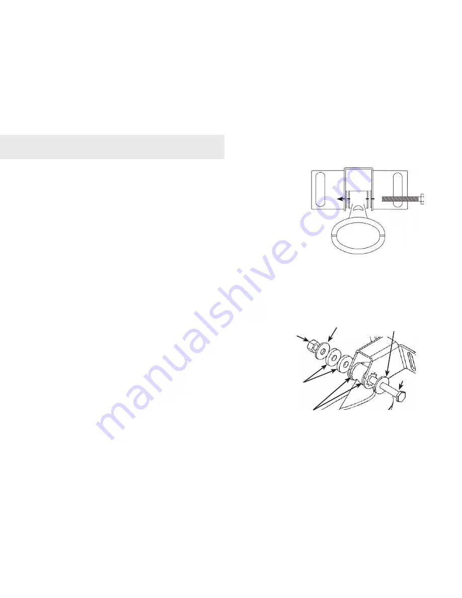
C. Assembling the Transducer bracket

After determining the correct position for the ratchets, 

loosely assemble the transducer and bracket assembly.

Lock nut

Metal washer

Rubber washers

Ratchets

Metal washer

Bolt

Installation

Summary of Contents for Elite 5 Sonar/GPS

Page 1: ...Installation Operation manual Elite 5 Sonar GPS Elite 5m GPS Installation Operation manual ...

Page 2: ...is unit are by infoUSA copyright 2001 2008 All Rights Reserved infoUSA is a trademark of infoUSA Inc Additional mapping data Copyright 2008 by Maptech Inc Navico may find it necessary to change or end our policies regulations and special offers at any time We reserve the right to do so without notice All features and specifications subject to change without notice Visit our website www lowrance co...

Page 3: ...ar Operation Elite 5 20 Viewing Sonar History 20 Sensitivity 21 Depth Range 22 Frequency 23 Sonar Options menu 23 Chart Operation 25 Waypoints Routes Trails 26 Creating a route 27 Navigating a route 29 To cancel navigation 30 Creating trails 31 Navigating a trail 32 Settings Menu 34 System 34 Navigation 36 Sonar 38 Installation menu 39 Alarms 40 Units 40 Simulator Advanced Mode 40 Index 41 Specifi...

Page 4: ...racket Recommended Tools and Supplies not included Drill Marine grade above or below waterline sealant 1 25mm or 5 8 15mm drill bit Marine grade epoxy Shoot thru hull install only 29 0 136 3mm drill bit Zip ties trolling motor mount Phillips Slotted head screwdriver TMB S bracket kit Skimmer trolling motor mount NOTE This majority of this installation does not apply to the Elite 5m since it does n...

Page 5: ...n as random lines or dots The unit also could lose bottom signal when the boat is on plane B Aligning Ratchets on Transducer bracket You will use the ratchets to ensure the transducer is installed parallel to the ground Insert the ratchets in the 1 bracket with the letter A aligned with the dot stamped on the outside of the transducer bracket Good locations Poor locations NOTE Mount the transducer...

Page 6: ... Reinsert the ratchets into the bracket this time with the letter B aligned with the dot stamped in the bracket Reassemble the transducer and bracket and place it against the transom Check to see if the transducer will adjust so its face is parallel with the ground Repeat this 5 process until the transducer can be adjusted so its face is parallel with the ground C Assembling the Transducer bracket...

Page 7: ...cable near the transducer If you need to drill a hole in the transom to pass the connector through the hole size will depend on the connector on the end of the transducer s cable E Make a test run to determine the results After the transducer is installed make a test run to ensure the transducer is installed properly Use the slots in the transducer mounting bracket to loosen the screws and slide t...

Page 8: ...ted so the nose of the transducer is facing the bow front of the boat If the transducer has a built in temp sensor it will only show the temperature of the hull not the water temp Before you epoxy the transducer to the hull make sure the area is clean dry and free of oil or grease The surface of the hull must be flat so the entire transducer face is in contact with the hull Also make sure the cabl...

Page 9: ... epoxied into position the transducer can be very difficult to remove Press the transducer into the epoxy turning it to force out any 4 air bubbles from under the transducer face Make sure there are no air pockets in the epoxy layers Stop pressing when it bottoms out on the hull Apply pressure 5 to hold the transducer in place while the epoxy sets Be careful not to move the transducer while the ep...

Page 10: ... with the TMB S 1 bracket attach the skimmer transducer to the bracket as shown in the diagram Slide the adjustable strap hose clamp through 2 the plastic bracket on the skimmer transducer or through the Pod transducer slots and then slip the strap around the trolling motor Position the transducer so its face is pointing straight down when the trolling motor is in 3 the water Flat washer Lock nut ...

Page 11: ...he transducer cable for the trolling motor to turn freely Mounting display unit Before mounting the display unit mount make sure there is nothing in the area that will obstruct the display unit when it is installed on the bracket Adjustable strap Plastic ties not included Transducer cable Installation ...

Page 12: ...unting surface push the cables through the 3 mounting surface and then pull them through the cabling hole in the center of the bracket Align the mounting bracket with the four mounting holes and use the supplied screws to 4 fasten it to the mounting surface Connect the display unit to the bracket mount 5 Connecting to Power Connect the black wire to a ground 1 Attach a 3 Amp fuse to the end of the...

Page 13: ...11 Installation 12V Optional paddlewheel speed temp sensor Optional temp sensor Black ground wire 3 Amp fuse Red power wire Speed temp port also used for NMEA 0183 Power port External GPS port ...

Page 14: ...from the System menu and press Enter Selecting a GPS Source Select GPS Source from the System menu and press Enter Select internal or external and press Enter ZOOM Keys used to zoom in zoom out press and hold both keys to create Man Overboard waypoint PAGES Opens pages menu allows you to select a page to view KEYPAD controls cursor selects items on menus MENU Opens settings context and page menus ...

Page 15: ...art pages have menus that can only be accessed when those pages are displayed Basic Operation Pages menu Steer page Settings menu Sonar Page Elite 5 only Sonar menu Chart Sonar page Elite 5 only Chart or sonar menu will appear depending on which panel is active Press the Pages key twice to switch active panels Chart page Chart menu ...

Page 16: ...press the keypad left decrease or right increase On Off features Select an on off menu item and press Enter to turn it on off Dropdown menus Press the keypad up down to select the desired item and press Enter Accessing menu items The keypad and enter key are used to select menu items and open submenus Use the keypad to highlight the desired item and press Enter Basic Operation Settings menu ...

Page 17: ...o specific fishing conditions Elite 5 only Entering text Some functions like naming a waypoint route or trail will require you to input text To input text Use the keypad to select the desired 1 character and press enter Repeat Step 1 for each character 2 When entry is completed highlight 3 OK and press enter Basic Operation Switches keyboard between Alpha and QWERTY layout Switches letters to uppe...

Page 18: ...ter Bottom brown blue background higher ASP slightly lower chart speed Cursor The keypad moves the cursor around the display allowing you to scroll the map select map items and review sonar history Elite 5 only Press Menu and select Return to vessel to clear the cursor Advanced Mode Enables advanced features and settings Advanced Mode features Colorline Enables manual control of colorline Surface ...

Page 19: ...nt Track Compass Direction to waypoint Navigation information Sonar Page Displays the water column moving from right to left on your unit s screen On the right side of the screen the Amplitude Scope bar previews echoes about to appear on the display Fish arches Surface Clutter Overlay Data Cursor Depth Location and depth Frequency Range Scale Amplitude Scope Colorline ...

Page 20: ... key twice to switch active panels Chart Sonar Page Chart Page Consists of map that moves in real time as you move By default the map is shown from a birds eye view with North at the top of the screen Current location Waypoint Current location distance to destination Depth contours Zoom Range ...

Page 21: ...u and select Add Press Enter Select a category from the Configure 5 Items to show screen Press Enter Press 6 Menu and select Return to overlay Press 7 Menu select Done Configuring and press Enter Show Shows hides selected overlay data on the display Customizing Overlay Data Overlay Data can be resized moved or removed from the display from the Overlay data menu Press Menu from the Overlay Data scr...

Page 22: ... affect the appearance of the display Sonar Operation Elite 5 Using your Sonar This section covers sonar operation which includes viewing sonar history and using sonar menus con text menus and submenus Information is arranged in the same order as the menus Viewing Sonar History You can review your recent sonar history by moving the cursor to the left until the screen starts to move in reverse Blue...

Page 23: ...w Waypoint Adjust Advanced Mode Depth Range Overlay Frequency Sonar Options Advanced Mode Sonar Operation Elite 5 Adjust Advanced Mode only Used to make adjustments to Sensitivity and Colorline Sensitivity Controls the level of detail shown on the display Too much detail will clutter the screen Conversely desired echoes may not be displayed if Sensitivity is set too low New waypoint menu Waypoint ...

Page 24: ... the needs for adjustments Auto Sensitivity is turned on by default Depth Range Selects the section of the water column from surface to bottom shown on the display Custom Range Upper and Lower Limits Advanced Mode only Used to select the upper depth and lower depth of a desired portion of the water column allowing you to select a range that does not include the water surface Upper and lower limits...

Page 25: ...for more water coverage Sonar Operation Elite 5 Custom range menu Ping Speed Advanced Mode only Controls the rate the transducer uses to send sonar waves into the water Sonar Options menu Accesses sonar display settings and configuration options Split Zoom and Split Flasher Switches the sonar display from full screen sonar to a split screen view Split frequency sonar view Frequency menu Split Flas...

Page 26: ...rches Fish ID is not as effective a fish finding method as the default fish arch setting Ice Mode Turns on a package of sonar settings that enhance the performance of your unit when ice fishing Stop Sonar Pauses the sonar chart allowing you to get a closer look at sonar echoes Overlay Data and Settings Overlay Data is covered in the Basic Operation section Settings accesses the Settings menu but w...

Page 27: ... and options like map orientation and waypoints routes and trails New Waypoint Creates a waypoint at your current location or at the cursor position When the cursor is on the screen waypoints will be saved at the cursor position conversely if the cursor is not displayed onscreen waypoints will be saved at your current position Chart menu Waypoints Routes Trails Orientation Overlay data Settings me...

Page 28: ...ils Press the keypad left right to toggle between waypoint routes and trails tabs Edit Allows you to edit the name icon and latitude longitude of a selected waypoint Chart Operation Waypoints Screen Waypoints menu New Edit Waypoints menu Show Delete Delete all Sort Save to card Load from card ...

Page 29: ... a selected waypoint Delete All deletes all waypoints Sort Controls how the waypoints list will be sorted by name or by nearest Routes Screen Used to create edit navigate and delete routes Use the keypad to highlight the Routes tab to access the Routes screen Creating a route Routes can be created by inserting waypoints from the waypoints list or by using the cursor to position new points on the c...

Page 30: ... Enter Press 7 Menu and select Add to end to add another waypoint to the route Repeat Steps 5 7 8 When the route is complete highlight the 9 Accept button on the New Route screen and press Enter Chart Operation Add waypoints from list or Points from chart Route waypoint menu Shows selected route waypoint on the chart Inserts waypoint between existing route waypoints Adds waypoint to end of the rou...

Page 31: ...rom chart and press Enter The chart screen will appear Move the cursor to the desired location 3 Press Enter to set a waypoint Repeat Step 3 to add more route 4 waypoints Press 5 Menu and select Stop inserting Press Enter Highlight the 6 Accept button and press Enter Navigating a route Routes can be navigated in forward or reverse Select the desired route 1 on the Route screen and press Menu Route...

Page 32: ...e and Delete All Delete is used to delete individual routes Delete All removes all routes To cancel navigation Press 1 Menu from the chart screen Select 2 Navigation and press Enter Highlight 3 Cancel and press Enter Select 4 Yes and press Enter Edit and New Route menus Used to edit create routes route names and to turn on off the route display That allows you to display only desired routes on the...

Page 33: ...ustomize the trail name and color from the New Trail menu Chart Operation To create a trail Select 1 New and press Enter The New Trail menu will appear Use the keypad 2 to highlight Record and press Enter to make the trail active inactive Select 3 Save and press Enter Routes screen Routes menu Trails menu New Trail menu Edit Trail menu Delete All Delete Load from card Save to card ...

Page 34: ...ws you to show hide trails on the map display preventing the screen from being cluttered with trails The Record command allows you to record or resume recording a desired trail Turns on off trail display on map Turns on off trail recording Edit Trails menu Edit and New Trail menus Allows you to edit create trails select trails names trail color trail display and the trail being recorded You can al...

Page 35: ... is used to remove individual trails Delete All removes all trails Orientation Allows you to select North Up or Course Over Ground COG as the map orientation Overlay Data and Settings Overlay Data is covered in the Basic Operation section Settings accesses the Settings menu but will only be shown on the map when the unit is in Advanced mode North Up COG ...

Page 36: ...dio and advanced mode Settings System menu Language menu Time menu GPS status screen Restore defaults message Displays software information screen GPS Source menu Tmp Spd port menu Settings menu NMEA 0183 Advanced mode only Chart Settings Sonar Settings System Settings Navigation Settings Alarms Simulator Unit Settings Advanced mode ...

Page 37: ...nitors the location of satellites in view and the quality of the unit s satellite lock on GPS Source Selects the type of GPS an tenna used by your unit Tmp Spd port Selects the type of device connected to the unit s Temp Speed port Advanced Mode Enables features and settings only available with unit in Advanced Mode Restore Defaults Switches the unit back to default settings About Displays softwar...

Page 38: ...ings Controls whether bearing will be calculated using True North or Magnetic North settings Magnetic Variation Controls whether magnetic variation will be calculated using Automatic or Manual settings Navigation Controls Arrival Radius and Off Course distance settings and is used to turn on off WAAS MSAS EGNOS Arrival Radius Sets arrival radius threshold for the Arrival alarm When the selected ar...

Page 39: ...Displays base values for latitude and longitude making it easier to get a general idea of your location on the latitude longitude scale Waypoints Routes and Trail displays From the Chart Settings menu you can turn on off waypoint route and trail display properties Turning off display properties allows you to get a better view of the map if the screen becomes cluttered with waypoints routes and or ...

Page 40: ...anual Mode In this mode the unit sends sonar signals pings only to the depth range you select instead of auto matically searching for the bottom That makes it easier to focus on suspended targets Fishing Mode Enhances the performance of your unit by providing preset packages of sonar settings geared to specific fishing conditions For more information about fishing modes refer to the Basic Operatio...

Page 41: ...he transducer to the keel or from the transducer to the water surface Keel Transducer Keel Offset 3 5 feet Before setting keel offset measure the distance from the transducer to the lowest part of the keel If for example the keel is 3 5 feet below the transducer it will be input as 3 5 feet Temperature calibration Calibrates data from one temp sensor with data from another temp source to ensure th...

Page 42: ...de only Anchor sounds alarm when vessel moves a selected distance Advanced Mode only Shallow sounds alarm when vessel enters water shallower than the selected shallow threshold Fish sounds alarm when a fish symbol Fish ID appears on the sonar screen Units Allows you to select the unit of measure for Distance Speed Depth and Temperature when the unit is in Advanced mode Simulator Simulates GPS and ...

Page 43: ...etic Variation 36 Man Overboard waypoint 12 Manual Mode 38 Menu operation 13 N Navigating a route 29 Navigating a trail 32 Navigation menu 36 Noise Rejection 38 O Off Course Distance 36 Orientation 33 Overlay Data 19 P Ping Speed 23 R Restore defaults 16 Routes Screen 27 S Sensitivity 21 Set Language 34 Settings Menu 34 Simulator 40 Sonar History 20 Sonar Menu 20 Sonar Options menu 23 Sonar Page 1...

Page 44: ...a new vessel by a Certified Approved Navico Boatbuilder the date that such vessel was purchased by the first retail customer General Case Size 5 4 H 134mm x 6 8 W 174mm 6 H 152mm with bracket Display 5 diagonal Enhanced Solar MAX 480x480 color TFT LCD Backlight Cold cathode fluorescent lamp 11 levels Communications NMEA 0183 Shared devices supported VHF and Autopilot through NMEA 0183 Power Transm...

Page 45: ...hafts costs associated with software updates where the product is not faulty differences in material coloring or size that may exist between actual products and the pic tures or descriptions of such replacement of missing components from the package of any product not purchased from an authorized Navico dealer or agent The product including any associated electronics charts is an aid to navigation...

Page 46: ... this Agreement Upon termina tion you will promptly return all products containing one or more Databases to us Prices and programs are subject to change without notice 5 This License Agreement shall be governed by the laws of the State of Oklahoma and 6 comprises the complete and exclusive understanding between you and us concerning the above subject matter Databases Limited Warranty We our or us ...

Page 47: ...____________________ Number of Motors check one 1 2 3 4 Engine Horsepower check one 9 15 16 25 26 50 51 75 76 125 126 175 176 225 226 250 250 Motor Type check one Outboard Inboard Sterndrive Jetdrive Other Boat Length feet 17 17 20 21 25 26 30 31 35 36 40 41 45 46 50 51 Water Type check one Fresh Salt Brackish All of the above Age check one 0 25 26 35 36 45 46 55 56 65 66 How often do you use your...

Page 48: ......

Page 49: ......

Page 50: ......

Page 51: ... your unit To locate a dealer near you see the instructions in paragraph number 1 below Accessory Ordering Information LEI Extras Inc is the accessory source for sonar and GPS products manufactured by Lowrance Electronics To order Lowrance accessories please contact 1 Your local marine dealer or consumer electronics store To locate a Lowrance dealer visit the web site www lowrance com and look for...

Page 52: ... Copyright 2009 All Rights Reserved Navico Holding AS 988 0180 01a Visit our website www lowrance com ...

Reviews: