Owners Manual
s
Rexnord
®
Planetgear™ 7000 Series Speed Reducers
(Page 18 of 32) Sizes Neptune, Neptune Plus, Orion Plus, Saturn Plus & Titan Plus
158-170
Rexnord
January 2015
3001 W. Canal St., Milwaukee, WI 53208-4200 USA
Supersedes 11-12
Telephone:414-342-3131 Fax: 414-937-4359 www.rexnord.com
NOTE
: Take care not to damage the shaft bearing
surface or seal surface.
12. With a hammer and punch, tap out the inboard and
outboard bearing cups from the housing.
NOTE
: Take care not to damage the bearing surface of
the housing.
6.3.3 DISASSEMBLING INPUT OR
OUTPUT SHAFT ASSEMBLIES TO
REPLACE BEARINGS (Neptune and
Neptune Plus Input and Output)
1. Remove endbell from reducer; reference Section 6.3.1.
2. Remove seal carrier from endbell; reference Section
6.2.1.
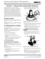
3. Support hub to expose the outboard side of the
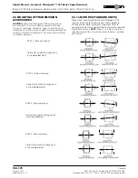
endbell; reference Figure 6.3.3.1A and Figure 6.3.3.1B.
SHAFT
PILOT
OUTBOARD
BEARING CONE
FLAT
PUNCH
OUTBOARD END OF SHAFT
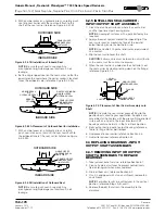
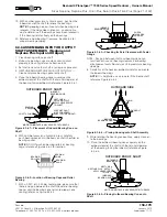
Figure 6.3.2.3 Removal of Outboard Bearing Cone
(Option #2)
NOTE
: Allow space between the shaft extension and
the working surface.
4.
NEPTUNE AND NEPTUNE PLUS INPUT ONLY
-
Remove pipe plug on housing near outboard end to
allow access to socket head cap screw on clampnut
5. Loosen socket head cap screw on clampnut.
6. Remove clampnut from shaft. Store in clean spot.
NOTE
: A wedge can be used to spread the clampnut
in order to ease removal.
7. Remove tongued washer from shaft. Store in clean spot.
8. With an arbor press or a hydraulic press, press on the
outboard end of the shaft to break free the outboard
bearing cone.
9. At this time, the shaft will be free and can be separated
from the housing. The outboard bearing cone will be
free to remove and discard.
CAUTION
: The input and output shafts are heavy.
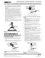
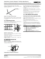
10. To remove the inboard bearing from the shaft, one of
two procedures can be used. 1.) Support the shaft by
the bearing cone with the outboard end of the shaft
facing up. With an arbor press or hydraulic press,
press down on the inboard end of the shaft; reference
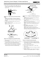
Figure 6.3.3.2. 2.) With a hammer and punch, carefully
strike the bearing cone towards the outboard end of
the shaft; reference Figure 6.3.3.3.
SUPPORT
BLOCK
PIPE PLUG
CLAMPNUT
TONGUED
WASHER
SUPPORT
BLOCK
OUTBOARD SIDE
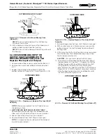
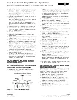
Figure 6.3.3.1A — Neptune and Neptune Plus Input Shaft
Assembly
SUPPORT
BLOCK
CLAMPNUT
BEARING
SPACER
BEARING SPACER
SUPPORT
BLOCK
OUTBOARD SIDE
Figure 6.3.3.1B — Neptune/Neptune Plus Output Shaft
Assembly
OUTBOARD END OF SHAFT
SUPPORT
BLOCKS
INBOARD
BEARING CONE
6.3.3.2 — Removal of Outboard Bearing Cone (Option #1)
Summary of Contents for CD-1261
Page 1: ... 0 1 2121 3 4 1 5 6 ...
Page 2: ... ...
Page 3: ... ...
Page 4: ... ...
Page 5: ... ...
Page 6: ... 0 1 2 3 4 5 6 5 6 7 1 1 5 6 5 6 5 6 1 0 0 ...
Page 7: ... ...
Page 8: ... 0 1 2 0 3 0 ...
Page 9: ... ...
Page 10: ... 0 12 2 0 3 4 5 5 5 0 0 ...
Page 11: ... 6 12 0 0 7 5 5 0 8 0 8 5 0 50 9 4 12 0 0 9 4 0 9 64 0 5 0 0 1 0 0 ...
Page 12: ... 0 2 0 0 3 0 6 6 6 6 6 0 0 0 5 5 0 6 0 ...
Page 14: ... ...
Page 15: ... 0 0 1 1 2 1 1 3 0 4 5 1 0 1 0 0 2 1 2 1 0 0 0 2 1 1 1 1 1 0 0 0 1 0 0 0 1 0 1 6 1 1 ...
Page 17: ... 1 0 3 0 0 1 1 1 71 0 0 1 1 1 0 1 1 ...
Page 18: ... ...
Page 25: ... 8 ...
Page 28: ... 1 7 4 0 4 1 4 1 1 4 1 1 1 4 85 4 4 1 4 1 4 0 6 4 1 1 1 01 0 1 4 6 4 1 1 4 L 1 ...
Page 29: ... 4 ...
Page 30: ... 0 1 2 3 24 3 5 6 4 5 6 4 5 5 1 5 4 74 8 5 9 1 4 27 3 5 4 74 8 5 5 29 13 27 3 1 29 13 5 1 ...
Page 31: ... 8 8 80 1 2 3 5 6 4 5 6 4 5 5 1 5 A 9 1 B 4 27 3 888 7 8 0 B 4 C D 5 29 13 B 27 3 888 7 29 13 ...
Page 32: ... 4 24 3 5 6 4 5 6 4 5 5 4 7 M 7 4 7 N 2 0 7 2 M 0 N M ...
Page 35: ... 8 G 8 0 G 4 88 8E 1 2 3 5 6 4 5 6 4 5 5 1 4 1 4 27 3 1 088 7 5 4 1 5 29 13 H 27 3 088 7 ...
Page 36: ... E 5 ...
Page 37: ... 9 4 5 H 0 1 2034 2034 2034 2034 0 5 1 6 71 6 1 2 1 1 1 0 1 81 1 9 9 ...
Page 38: ... 1 5 1 5 1 3 05 3 1 0 1 1 6 A 6 1 A 6 B 1 6 B 6 1 1 1 6 6 6 2 9 0 6 ...
Page 39: ... 0 ...
Page 40: ... 0 0 ...
Page 42: ......
Page 43: ... 0122 3 4 5 6 4 4 4 4 5 4 4 4 4 4 7 7 4 4 6 4 4 5 5 4 5 8 8 3 5 3 5 3 5 3 5 5 ...
Page 44: ... 0 0 0 0 0 0 0 0 0 0 1 1 2 3 0 3 3 0 0 33 0 3 0 3 3 0 ...
Page 46: ... 011 2 3 3 4 3 2 5 5 6 ...
Page 47: ... 011 2 3 4 5 3 6 3 7 7 2 4 ...
Page 48: ... 00 1 2 3 4 3 5 5 5 5 5 3 1 1 2 2 6 1 1 1 5 5 7 5 5 5 5 ...
Page 49: ... 0122 3 4 5 6 7 4 8 4 4 8 4 4 8 5 5 5 5 5 5 5 5 5 5 5 5 ...
Page 50: ... 0 11 2 2 2 2 2 3 4 5 0 5 3 6 7 6 6 8 9 8 9 6 6 8 9 0 1 1 1 1 1 8 9 1 1 1 5 ...
Page 51: ... 011 2 3 4 5 4 2 2 2 6 2 6 6 3 3 3 3 3 3 3 ...
Page 53: ... 011 2 3 4 5 4 2 6 33 2 33 6 6 6 ...
Page 54: ... 011 2 3 3 3 3 4 5 4 33 2 33 6 3 3 3 ...
Page 56: ... 0122 3 4 5 6 7 8 4 4 5 8 4 4 8 9 9 9 8 4 4 4 88 8 8 8 ...
Page 57: ... 0 1 1 1 2 1 3 1 1 1 0 1 1 1 4 1 1 ...
Page 58: ... ...
Page 59: ... ...
Page 96: ...Bearing Maintenance Guide x Lubrication x Troubleshooting ...
Page 97: ......
Page 98: ......
Page 99: ......
Page 100: ......
Page 101: ......
Page 102: ......
Page 103: ......
Page 104: ......
Page 105: ......
Page 106: ......
Page 107: ......
Page 108: ......
Page 109: ......
Page 110: ......
Page 111: ......
Page 112: ......
Page 113: ......
Page 114: ......
Page 115: ......
Page 116: ......
Page 117: ......
Page 118: ......
Page 119: ......
Page 120: ......
Page 121: ......
Page 122: ......
Page 123: ......
Page 124: ......
Page 125: ......
Page 126: ......
Page 165: ... 0 0 1 2 3 4 5 6 52 3 52 3 7 8 4 6 52 4 6 1 9 9 9 9 9 ...
Page 166: ... 0 5 9 9 2 2 4 6 4 6 4 6 7 8 7 8 2 4 6 4 7 8 7 8 2 4 6 4 6 52 A ...
Page 167: ... 0 0 1 2 1 2 3 4 2 1 2 3 4 ...
Page 168: ... 0 2 1 2 3 3 4 2 1 2 3 4 2 ...
Page 194: ......
Page 195: ......
Page 196: ......
Page 218: ......
Page 219: ......
Page 234: ...15 Notes Model 121 Regulators Brochure ...
Page 236: ......

