IM-995
Installation, Operation & Maintenance Manual
18
Optional Accessories
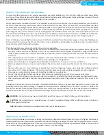
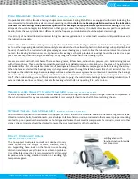
1. Turning Gear
— A turning gear is sometimes used in high temperature applications where the fan is exposed to high
temperature gases when not in operation. The wheel and shaft can expand unevenly due to the temperature when sitting
idle, which can cause vibration at startup and/or a permanent set to the rotor. The turning gear slowly turns the fan from the
outboard side while it is not operating, providing for even thermal expansion. It starts automatically when the fan shuts down
and disengages automatically when the fan starts up again. More specific information will be provided for each application.
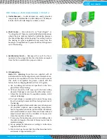
2. Shaft Seals
—
The standard shaft seal is a wire inserted fiberglass
tacky cloth element retained with an aluminum retaining plate and
clips. Other configurations of shaft seals are available for special
applications, such as when it is necessary to keep the shaft seal as
gas tight as possible. Shaft seal application manuals are provided
in Fan Engineering FE-700 available on www.tcf.com. Other seals
such as stuffing boxes, mechanical seals and carbon ring seals need
special attention. It is imperative that after the fan has been leveled,
shimmed, fastened to the foundation and ducted the shaft and seal
be checked for concentricity and angularity. The seal must not bind
when the shaft is rotated. Stuffing box packing material must not be
compressed too tight by the gland or overheating will occur. Monitor
temperature for a period of time. Connect a purge if specified.
Carbon ring seals have pins which prevent ring rotation.
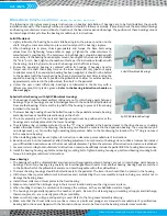
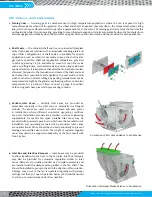
3. Variable Inlet Vanes
— Variable inlet vanes are provided as
assemblies internally in the inlet cone or externally in a flanged
cylinder. The vanes are used to control volume and save power
in installations where different volumetric operating conditions
are used. Installation manuals are provided in other engineering
supplements for specific fan types. Variable inlet vanes may be
provided with powered operators in which case the manufacturer’s
installation and operating manuals will be provided. Inlet vanes
are unidirectional. Vanes should be stroked periodically to prevent
binding and possible seizure.
Note: The weight of customer supplied
vanes may need to be supported indepently of the fan. Consult with
Twin City Fan.
4. Inlet Box and Inlet Box Dampers
— Inlet boxes may be provided
to allow transition from a duct to the fan inlet. Inlet box dampers
may also be provided for volumetric regulation similar to inlet
vanes. Dampers are usually provided as a complete assembly and
are installed with the damper axles parallel to the fan shaft. They
should be installed to pre-spin the air in the direction of fan rotation.
Damage may occur if the fan is operated regularly with damper
settings less than 30% open. Operation below 30% should be limited
to start-up or occasional periods of low duration.
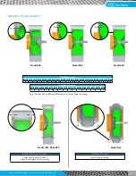
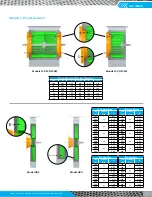
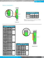
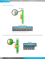
Orientation of Damper Blades Relative to Fan Rotation
Orientation of Inlet Vanes Relative to Fan Rotation
Summary of Contents for CD-1261
Page 1: ... 0 1 2121 3 4 1 5 6 ...
Page 2: ... ...
Page 3: ... ...
Page 4: ... ...
Page 5: ... ...
Page 6: ... 0 1 2 3 4 5 6 5 6 7 1 1 5 6 5 6 5 6 1 0 0 ...
Page 7: ... ...
Page 8: ... 0 1 2 0 3 0 ...
Page 9: ... ...
Page 10: ... 0 12 2 0 3 4 5 5 5 0 0 ...
Page 11: ... 6 12 0 0 7 5 5 0 8 0 8 5 0 50 9 4 12 0 0 9 4 0 9 64 0 5 0 0 1 0 0 ...
Page 12: ... 0 2 0 0 3 0 6 6 6 6 6 0 0 0 5 5 0 6 0 ...
Page 14: ... ...
Page 15: ... 0 0 1 1 2 1 1 3 0 4 5 1 0 1 0 0 2 1 2 1 0 0 0 2 1 1 1 1 1 0 0 0 1 0 0 0 1 0 1 6 1 1 ...
Page 17: ... 1 0 3 0 0 1 1 1 71 0 0 1 1 1 0 1 1 ...
Page 18: ... ...
Page 25: ... 8 ...
Page 28: ... 1 7 4 0 4 1 4 1 1 4 1 1 1 4 85 4 4 1 4 1 4 0 6 4 1 1 1 01 0 1 4 6 4 1 1 4 L 1 ...
Page 29: ... 4 ...
Page 30: ... 0 1 2 3 24 3 5 6 4 5 6 4 5 5 1 5 4 74 8 5 9 1 4 27 3 5 4 74 8 5 5 29 13 27 3 1 29 13 5 1 ...
Page 31: ... 8 8 80 1 2 3 5 6 4 5 6 4 5 5 1 5 A 9 1 B 4 27 3 888 7 8 0 B 4 C D 5 29 13 B 27 3 888 7 29 13 ...
Page 32: ... 4 24 3 5 6 4 5 6 4 5 5 4 7 M 7 4 7 N 2 0 7 2 M 0 N M ...
Page 35: ... 8 G 8 0 G 4 88 8E 1 2 3 5 6 4 5 6 4 5 5 1 4 1 4 27 3 1 088 7 5 4 1 5 29 13 H 27 3 088 7 ...
Page 36: ... E 5 ...
Page 37: ... 9 4 5 H 0 1 2034 2034 2034 2034 0 5 1 6 71 6 1 2 1 1 1 0 1 81 1 9 9 ...
Page 38: ... 1 5 1 5 1 3 05 3 1 0 1 1 6 A 6 1 A 6 B 1 6 B 6 1 1 1 6 6 6 2 9 0 6 ...
Page 39: ... 0 ...
Page 40: ... 0 0 ...
Page 42: ......
Page 43: ... 0122 3 4 5 6 4 4 4 4 5 4 4 4 4 4 7 7 4 4 6 4 4 5 5 4 5 8 8 3 5 3 5 3 5 3 5 5 ...
Page 44: ... 0 0 0 0 0 0 0 0 0 0 1 1 2 3 0 3 3 0 0 33 0 3 0 3 3 0 ...
Page 46: ... 011 2 3 3 4 3 2 5 5 6 ...
Page 47: ... 011 2 3 4 5 3 6 3 7 7 2 4 ...
Page 48: ... 00 1 2 3 4 3 5 5 5 5 5 3 1 1 2 2 6 1 1 1 5 5 7 5 5 5 5 ...
Page 49: ... 0122 3 4 5 6 7 4 8 4 4 8 4 4 8 5 5 5 5 5 5 5 5 5 5 5 5 ...
Page 50: ... 0 11 2 2 2 2 2 3 4 5 0 5 3 6 7 6 6 8 9 8 9 6 6 8 9 0 1 1 1 1 1 8 9 1 1 1 5 ...
Page 51: ... 011 2 3 4 5 4 2 2 2 6 2 6 6 3 3 3 3 3 3 3 ...
Page 53: ... 011 2 3 4 5 4 2 6 33 2 33 6 6 6 ...
Page 54: ... 011 2 3 3 3 3 4 5 4 33 2 33 6 3 3 3 ...
Page 56: ... 0122 3 4 5 6 7 8 4 4 5 8 4 4 8 9 9 9 8 4 4 4 88 8 8 8 ...
Page 57: ... 0 1 1 1 2 1 3 1 1 1 0 1 1 1 4 1 1 ...
Page 58: ... ...
Page 59: ... ...
Page 96: ...Bearing Maintenance Guide x Lubrication x Troubleshooting ...
Page 97: ......
Page 98: ......
Page 99: ......
Page 100: ......
Page 101: ......
Page 102: ......
Page 103: ......
Page 104: ......
Page 105: ......
Page 106: ......
Page 107: ......
Page 108: ......
Page 109: ......
Page 110: ......
Page 111: ......
Page 112: ......
Page 113: ......
Page 114: ......
Page 115: ......
Page 116: ......
Page 117: ......
Page 118: ......
Page 119: ......
Page 120: ......
Page 121: ......
Page 122: ......
Page 123: ......
Page 124: ......
Page 125: ......
Page 126: ......
Page 165: ... 0 0 1 2 3 4 5 6 52 3 52 3 7 8 4 6 52 4 6 1 9 9 9 9 9 ...
Page 166: ... 0 5 9 9 2 2 4 6 4 6 4 6 7 8 7 8 2 4 6 4 7 8 7 8 2 4 6 4 6 52 A ...
Page 167: ... 0 0 1 2 1 2 3 4 2 1 2 3 4 ...
Page 168: ... 0 2 1 2 3 3 4 2 1 2 3 4 2 ...
Page 194: ......
Page 195: ......
Page 196: ......
Page 218: ......
Page 219: ......
Page 234: ...15 Notes Model 121 Regulators Brochure ...
Page 236: ......


