109
This connection should therefore be
made to an earthing point well away
from
the battery and from any fuel va-
pour area or moving parts. An engine
hanger bracket is often ideal.
5. Start the disabled vehicle in the usual
way and run at a fast idle.
6.
A spark will occur at the first disconnec
-
tion of a jumper cable, so it is essential
that the first disconnection is made
from the slave car earth. Both batteries
(especially the discharged one) will be
‘gassing’ heavily at this time and
if the
first disconnection is made at a battery
terminal, there is a danger that the hy-
drogen gas may be ignited by the spark
with a resultant explosion.
7.
Have the cause of the flat battery inves
-
tigated and rectified and trickle charge
the battery as detailed above.
WARNING
Both the final connection and the first
disconnection should be made away
from the battery to reduce the risk of
explosion or an electrical short circuit.
Use only jumper cables of adequate
cross-section, fitted with completely
insulated alligator clamps. The cables
must be long enough to allow that neither
cars nor cables touch each other.
WARNING
Follow all warnings and instructions of
the jumper cable manufacturer.
When connecting the jumper cables,
keep them away from moving engine
parts.
The two cars must not contact each
other, or current could flow as soon as
the positive terminals are connected.
When the first clamp on each cable is
connected, the other clamp on that cable
must be held carefully to make
sure it
does not come into contact with either
another cable clamp or either car.
Ensure that tools or metal watches or
jewellery do not contact the battery ter-
minals or electrically live components.
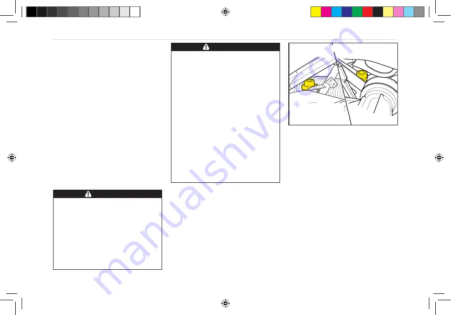
Inertia Switches
The safety inertia switches are designed
to operate on impact, typified by a vehicle
collision, to switch off the fuel pump, thus
minimising any fire hazard. The central
door locking will also be triggered to
unlock the doors.
The inertia switches are mounted on the
left hand and right hand backstays at the
extreme left and right hand sides of the
engine bay. The left hand inertia switch
is located ahead of the airbox, behind
the charge cooler reservoir (removed for
clarity in the above illustration). The right
hand inertia switch is located ahead of the
supercharger pulley.
Both are reset by pressing the diaphragm
buttons on the top of the switches.
ohe153
for clarity
Left side Right side
ELECTRICAL
Charge cooler
reservoir removed
INERTIA SWITCHES
E132T0324JA Federal Evora 400 From SOP OHB English Language.indd 109
15/08/2018 14:47:45


