background image

LORENZ MESSTECHNIK GmbH

Obere Schloßstr.131
73553 Alfdorf

 07172 / 93730-0

Fax 07172 /93730-22


E-Mail: [email protected] 

Technical changes reserved 

090327.docx 

Internet: 

www.lorenz-sensors.com


Page 9 of 12 


5.4 

Shielding Connection 

In  combination  with  the  sensor  and  the  external  electronics,  the  shield  forms  a Faraday  Cage.  By  this, 
electro-magnetic disturbances do not have any influence on the measurement signal. 

5.5 

Running of Measuring Cables 

Do  not  run  measuring  cables  together  with  control  or  heavy-current  cables.  Always  assure  that  a  large 
distance  is  kept  to  engines,  transformers  and  contactors,  because  their  stray  fields  can  lead  to 
interferences of the measuring signals. 
If  troubles  occur  through  the  measuring  cable,  we  recommend  to  run  the  cable  in  a  grounded  steel 
conduit.  

5.6 

Angle (Option) 

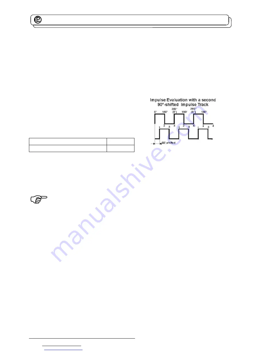
At angle or speed measurement, the pulses / revolutions 
are acquired. By a second transmitter trace, displaced by 
90° and flank evaluation, the pulses / revolutions can be  
quadrupled.  The  trace,  displaced  by  90°,  can  also  be 
used for the rotational direction detection. 
See corresponding data sheet for the output levels. 
 
Supply for angle sensor 
Stabilized supply voltage 

5 V ±25 mV 

Current consumption max. 

20 mA 


Measuring 

6.1 

Engaging 

The  warming-up  period  of  the  torque  sensor  is  approx.  5  min.  Afterwards  the  measurement  can  be 
started. 


The warming-up period of the torque sensor is approx. 5 min. 

6.2 

Direction of Torque 

Torque means clockwise or clockwise torque if the torque acts clockwise when facing the shaft end. In 
this case a positive electrical signal is obtained at the output. 
Torque  sensors  by  Lorenz  Messtechnik  GmbH  can  measure  both,  clockwise  and  counter-clockwise 
direction. 

6.3 

Static / Quasi-Static Torques 

Static and/or quasi-static torque is a slowly changing torque. 
The calibration of the sensors occurs statically on a calibration device. 
The applied torque may accept any value up to the nominal torque. 

6.4 

Dynamic Torques 

The static calibration procedure of torque sensors is also valid for dynamic applications. 
Note:  The  frequency  of  torques  must  be  smaller  than  the  natural  frequency  of  the  mechanical 
measurement setup. 
The band width of alternating torque must be limited to 70 % of the nominal torque. 


Summary of Contents for DR-1986

Page 1: ...lfdorf 07172 93730 0 Fax 07172 93730 22 E Mail info lorenz sensors com Technical changes reserved 090327 docx Internet www lorenz sensors com Page 1 of 12 Operation Manual for Torque Sensors For below...

Page 2: ...nd or getting caught by parts Coverings may Not grind Not rotate Coverings are also necessary outside of operating and motion travel areas of persons These demands can be modified if other sufficient...

Page 3: ...g Output 6 4 Mechanical Assembly 7 5 Electrical Connection 8 5 1 Pin Connection 8 5 1 1 Standard Version 8 5 2 Calibration Control 8 5 2 1 Calibration Control at Analog Output 8 5 3 Cable 8 5 4 Shield...

Page 4: ...for safety related interests for the sensor Remaining dangers must be minimized Remaining dangers of the torque measurement technique must be pointed out Human mistakes must be considered The construc...

Page 5: ...allation position of the torque sensor can be chosen freely Caution it is to be differentiated between measuring side and drive side see data sheet of the sensor http www lorenz sensors com 3 1 Mechan...

Page 6: ...the analog signal the measuring signal in digital form is much more disturbance free The remaining distance of the measuring signal within the sensor occurs in digital form completely Thus the measuri...

Page 7: ...ll torques 50 N m connect the sensor electrically during the assembly and observe the signal the measurement signal may not exceed the limit values Type DR 1986 The shaft of the torque sensor is desig...

Page 8: ...al GND 0 V E Excitation GND 0 V F Excitation 12 28 VDC G Angle A TTL H NC J NC K Calibration control L 2 0 V H 3 5 V L NC M Housing 5 2 Calibration Control Only use calibration control in unloaded con...

Page 9: ...n also be used for the rotational direction detection See corresponding data sheet for the output levels Supply for angle sensor Stabilized supply voltage 5 V 25 mV Current consumption max 20 mA 6 Mea...

Page 10: ...the device in natural resonance can lead to permanent damages 6 5 Speed Limits The maximum speed indicated in the data sheet may not be exceeded in any operating state 6 6 Disturbance Variables By di...

Page 11: ...Check evenness of flange surfaces Shaft overloaded Send to manufacturer Wrong torque indication Calibration not correct Re calibrate Sensor defect Repair by manufacturer Torque shunt Eliminate shunt...

Page 12: ...tocol Traceable calibrated measuring equipment is being used for the calibration The sensor data are being checked during this calibration 11 2 DKD Calibration The calibration of the sensor is carried...

Reviews: