


3DM-GX4
™
-45
™
Inertial Navigation System
User Manual
Sensor Measurements
22
4.
Sensor Measurements
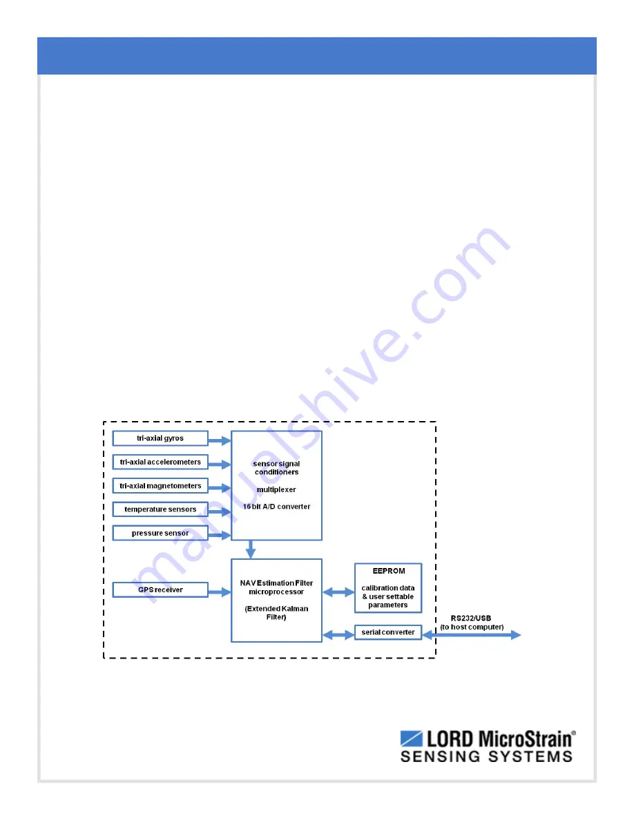
The 3DM-GX4-45
™
block diagram (
Figure 15 - 3DM-GX4-45™ Block Diagram
) describes its
primary hardware components and internal configuration. Integrated Micro-Electro-Mechanical
System (MEMS) sensors within the 3DM - GX4 - 45
™
are collectively known as the Inertial
Measurement Unit (IMU) and include tri-axial gyroscopes (gyros), tri-axial accelerometers, tri-axial
magnetometers, and a pressure altimeter. This technology provides direct measurements of
acceleration, angular rate, magnetic field, pressure, delta-Theta (change in acceleration), and
delta- v (change in velocity). Temperature and pressure sensors provide environmental
information for measurement compensation and altitude estimations. GPS information can be
read directly and is also used in the computed navigation estimations.
Computed estimations for position, velocity, and attitude (PVA), and attitude and heading
reference systems (AHRS) are available outputs on the 3DM- GX4 - 45
™
. To achieve these
estimations, the MEMS sensors are processed by a Navigation (NAV) Estimation Filter (EF)
microprocessor with an Extended Kalman Filter (EKF) . All measurements are temperature
compensated and are mathematically aligned to an orthogonal coordinate system. Additional user
settings such as measurement filtering, biasing, and tolerance values offer adjustments for specific
applications.
Figure 15 -
3DM-GX4-45
™
Block Diagram