- 11 -
Before start-up
06.13
Â
Thread the wire electrode through the inlet nozzle 26
and the central socket 8.
Â
Fold the swivel arm 25 down and secure in position
with the tilt levers 24.
Â
Switch on the welding power source at the main
switch.
7
Â
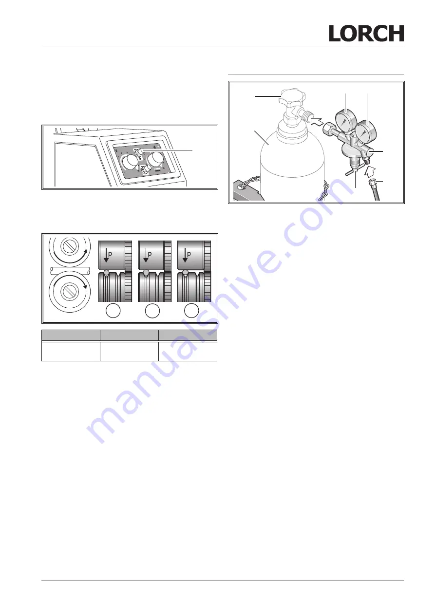
Press the wire feed button 7.
Â
Adjust the contact pressure using the regulation
screws on tilt lever 24 so that wire feed rollers 27 just
slip when the welding wire spool is stopped.
A
B
C
A
B
C
correct
Contact pressure
too high
Wrong wire feed
roller
Fig. 5:
Wire feed rollers
The wire must not be jammed or deformed.
Â
Adjust the contact pressure of the wire feed rollers
27 on the side of the inlet nozzle 26 to be less than
on the side of the central socket 8 in order to keep
the wire electrode under tension in the wire feed unit.
Â
Push the wire feed button 7 until the wire protrudes
from the torch neck by about 20 mm.
Â
Screw the contact tip matching the wire thickness into
the torch and cut off the protruding end of the wire.
10.4 Connecting the inert gas cylinder
34
31
33
36
35
32
30
Fig. 6:
Gas connection
Â
Place the inert gas cylinder 36 in a suitable location
and secure to prevent it from falling over.
The cylinder can be secured using a wall bracket or
cylinder trolley.
Â
Briefly open the gas cylinder valve 35 several times
in order to blow out any dirt particles that are present.
Â
Connect the pressure reducer 30 to the inert gas cyl-
inder 36.
Â
Screw the inert gas hose 32 to pressure reducer 30
and open the gas cylinder valve 35.
Setting the inert gas quantity
Â
Press the "Gas test" button 41.
9
Inert gas flows out.
9
The flow meter 31 indicates the gas quantity, and
the content pressure gauge 34 indicates the cylinder
content.
Â
Adjust the inert gas quantity at the setting screw 33.
Rule of thumb:
Gas volume = wire diameter x 10 l/min.


