4
LOOK-C INSTRUCTIONS
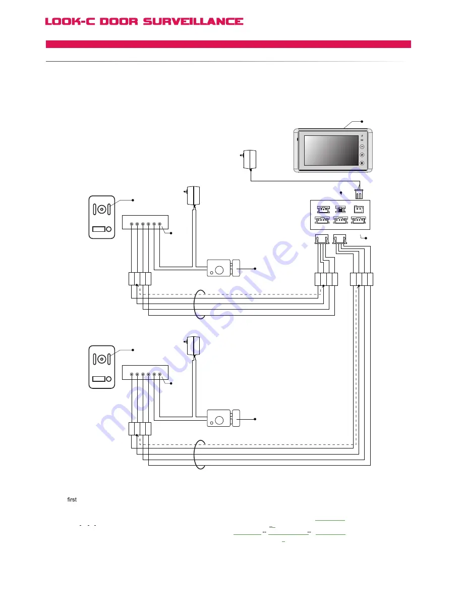
4 Wire - Camera Expanded
TWODOORSTATIONS
1
2
3
4
[1]
The
Doorstation connect to the JS-OS1 port.
[2]
The second Doorstation connect to the JS-OS2 port.
[3]
The electronic lock used for each Doorstation must be
of the Power on to Unlock type. Power can be external as
shown, or internal (see door lock page for options).
[4]
JP-VD jumper. To adjust the video impedance; keep the
jumper on the last Monitor and remove all on other Monitors.
When only one Monitor installed, keep the jumper (as in this
case). Jumper on the position by default.
[5]
System can be expanded to further monitors, see the
Multi-monitor setup pages for connection topologies.
[6]
When using two door stations
the
2 Way Input
menu
should be set from
0
to
1
on
1#
Monitor
go to
User Setup
>
Installer Setup
>
2 Way Input
and change the value to
1
.
AC ~
1R 2W 3Y 4B
1R 2W 3Y 4B
1# Electronic Lock
Adapter
Adapter
1# Door Station
Monitor
+
+
-
-
2# Door Station
AC ~
1R 2W 3Y 4B
1R 2W 3Y 4B
2# Electronic Lock
Adapter
+
+
-
-
AC ~
B
la
ck
Ye
llo
w
R
ed
W
hi
te
B
la
ck
Ye
llo
w
R
ed
W
hi
te
[6]
[3]
[3]
[5]
[4]
[1]
[2]
B
la
ck
Ye
llo
w
R
ed
W
hi
te
1R 2W 3Y 4B 2 1
B
la
ck
R
ed
[3]
B
la
ck
Ye
llo
w
R
ed
W
hi
te
1R 2W 3Y 4B 2 1
B
la
ck
R
ed
[3]
The H4.27 Monitor is equipped with Two Input connection ports which allows a user to connect two door stations
or one door station and one CCTV Camera directly. It is required that this monitor be menu set as Monitor #1 (Default).
Door station control is automatic. eg., when any Monitor activates the door unlock function, only the door latch
connected to the operating door station will be unlocked. H424 does not suport 2 Inputs. See MDS for other options.
JS-OS1
Input 1
Input 2
Output
JS-AP
Handset
75 Ohm
JP-VD
DC-IN
DC- DC+
JS-OS2
JS-VD
1R
12V
2W
4B
2W 3Y 4B
1R 2W 3Y 4B
1R 2W 3Y 4B


