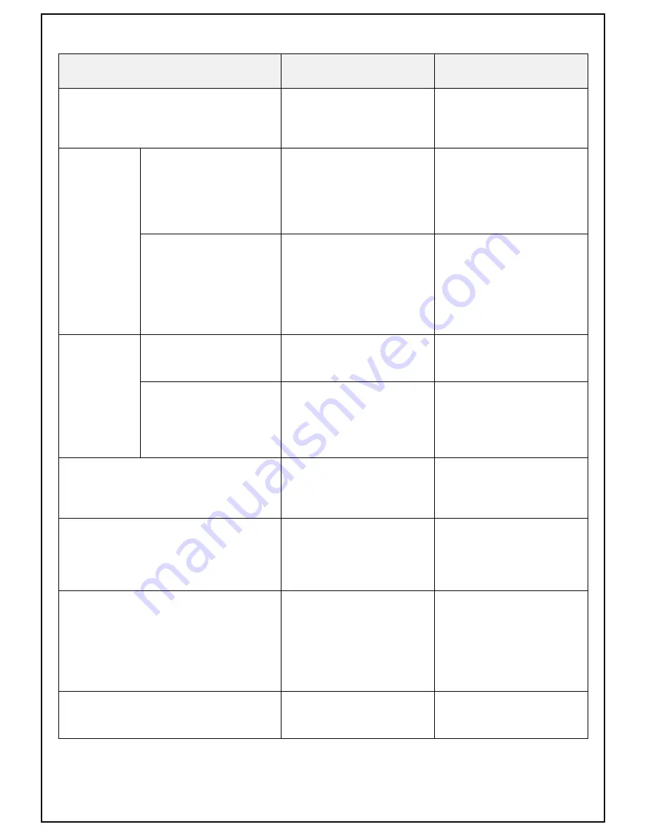
Longrun 610TC Operation Manual Download Page 8

■  TROUBLESHOOTING

√  If  all  recommended  action  have  been  checked  and  the  problem  persists,  please  contact  our  service 

center

SYMPTOMS

REASON

RECOMMENDED  ACTION

Cooling  fan  does  not  run  when  the  power  switch  is 

turn  on.

․   

No  input  voltage

․   

Fuse  (5A)  is  blown

․   

Power  switch  broke  down

․   

Cooling  fan  broke  down

․   

Verify  input  voltage

․   

Replace  Fuse  (5A)

․   

Replace  Power  switch

․   

Replace  Cooling  fan

Welding  wire 

does  not  go  out 

from  wire  feeder

Welding  wire  does  not  go  out 

when  pressing  the  inching  switch 

of  wire  feeder

․   

Fuse  (15A)  is  blown

․   

Wire  feeding  cable  does  not           

    connect  perfectly

․   

Motor  of  wire  feeder  broke  down

․   

Control  PCB  broke  down

․   

Replace  Fuse  (15A)

․   

Reconnect  Wire  feeding  cable  of   

    torch

․   

Replace  Motor  of  wire  feeder

․   

Replace  Control  PCB

Wire  feeding  has  no  problem 

when  pressing  the  inching 

switch,  but  Welding  wire  does 

not  go  out  from  wire  feeder 

when  pressing  the  torch  switch 

of  torch 

․ 

Torch  switch  connector  does  not     

    connect  perfectly

․   

Torch  switch  broke  down

․   

Control  PCB  broke  down

․ 

Reconnect  Torch  switch  connector

․   

Replace  Torch

․   

Replace  Control  PCB

Gas  does  not 

flow  from  torch

Gas  does  not  flow  from  torch 

when  the  GAS  CHECK  switch  is 

"GAS  CHECK"  position

․   

Close  the  valve  of  gas  tank

․   

Gas  check  switch  broke  down

․   

Open  the  valve  of  gas  tank

․   

Replace  Gas  check  switch

Gas  does  not  flow  from  torch 

when  pressing  the  torch  switch

․   

Torch  switch  connector  does  not   

    connect  perfectly

․   

Torch  switch  broke  down

․   

Control  PCB  broke  down

․ 

Reconnect  Torch  switch  connector

․   

Replace  Torch

․   

Replace  Control  PCB

Gas  flows  continuous  at  "WELDING"  position  of  GAS 

CHECK  switch

․   

GAS  CHECK  switch  broke  down

․   

Torch  broke  down

․   

Control  PCB  broke  down

․   

Replace  GAS  CHECK  switch

․   

Replace  Torch

․   

Replace  Control  PCB

It  does  not  adjust  the  welding  voltage  and  current  on 

the  wire  feeder

․   

Remote  control  connectors  of         

    wire  feeder  does  not  connect           

    perfectly

․   

Volume  broke  down

․   

Control  PCB  broke  down

․   

Reconnect  Remote  control               

    connectors  of  wire  feeder

․   

Replace  Volume

․   

Replace  Control  PCB

Arc  does  not  started

․   

Torch  cable  is  broke

․   

Torch  switch  connector  does  not   

    connect  perfectly

․   

Work  cable  does  not  connect         

    perfectly

․   

Torch  broke  down

․   

Control  PCB  broke  down

․   

Repair  Torch  cable

․   

Reconnect  Torch  switch  connector

․   

Reconnect  Work  cable

․   

Replace  Torch

․   

Replace  Control  PCB

Crater  does  not  work

․   

Crater  select  switch  broke  down

․   

Control  PCB  broke  down

    Contact  our  service  center

Summary of Contents for 610TC

Page 1: ...THYRISTOR CO2 MAG ARC WELDER OPERATION MANUAL DO NOT INSTALL OPERATE OR MAINTAIN THIS MACHINE WITHOUT READING THIS MANUAL AND PLEASE ALWAYS THINK BEFORE YOU ACT www worldwel com...

Page 2: ...city of all parts and quality cooling fan Adjustable crater voltage and current ITEM UNIT SPECIFICATION Input Voltage V 220 380 440 3 Phase 50 60Hz Rated Output Current A 600 Input Current rated outpu...

Page 3: ...insulating yourself from work and ground Use non flammable dry insulating material if possible or use dry rubber mats dry wood or plywood or other dry insulating material big enough to cover your full...

Page 4: ...parks and hot materials from welding can easily go through small cracks and opening to adjacent areas Avoid welding near hydraulic lines When not welding make certain no part of the electrode circuit...

Page 5: ...le to the power input cable on the rear of the machine For grounding the machine connect a ground wire to the ground terminal marked with the symbol is located on the rear panel of the machine Output...

Page 6: ...rent 5 Crater Voltage Volume Adjust the crater voltage 6 Power Lamp It indicates that the machine is on and input voltage is within acceptable range 7 Warning Lamp It indicates the thermal over load o...

Page 7: ...e torch switch the arc is turn off START UP Verify the voltage to be supplied from main power and turn on main power Position the crater switch to CRATER OFF or CRATER ON Turn on the power switch of m...

Page 8: ...rom torch Gas does not flow from torch when the GAS CHECK switch is GAS CHECK position Close the valve of gas tank Gas check switch broke down Open the valve of gas tank Replace Gas check switch Gas d...

Page 9: ...Block Diagram...

Page 10: ...4 Initial value On factory 40V welding voltage 3V Wire speed Adjust voltage and current of wire feeder when torch is ON It s saved when DIP S W is OFF 5 Magnet S W Selection of POWER INPUT ON If magn...

Page 11: ...tor speed setting 3phases 380V Initial setting on Factory Starting voltage 43V Starting Motor Speed 4V You can change Starting voltage and Starting motor speed using adjustable resistance of voltage a...

Page 12: ......

Page 13: ......

Page 14: ...1 10 Control Transformer 7630 1 11 Main PCB 610TC 1 12 SCR MTG200A 2 13 Distribution PCB 610TC 1 14 Hole CT TM3A300 04DA15 1 15 Resistor Discharge 400W 100 1 16 Main Transformer 610TC 1 17 Induction c...

Page 15: ...rchased Where Purchased Where you use Whenever you request replacement parts or information on this machine always supply the information you have recorded above The date number is especially importan...

Reviews: