background image

Automatic Cutoff Device

In the usual shutdown procedure, solution flow is turned off

before

the engine

is turned off, since solution that is allowed to settle in the still-hot fogger tube
can burn.

If the engine shuts off unexpectedly, for example if gas runs out, then you

may not have time to turn off solution flow beforehand.

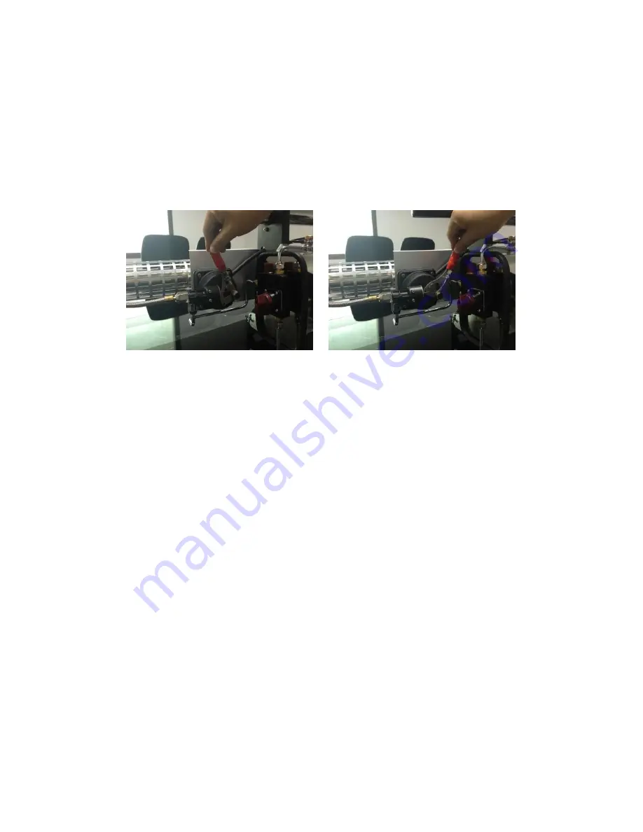
The optional automatic cutoff device immediately turns off solution flow

if the engine stops.

READY

DISABLED

If your unit is equipped with an automatic cutoff device, follow these

modified startup and shutdown procedures:

1.

Automatic cutoff should be DISABLED.

2. Start the engine as usual.

3. Turn solution tap to ON.

4.

Set automatic cutoff to READY by pushing the lever LEFT.

5. Begin spraying.

6. When you are done, turn solution tap to CLEAN, then OFF.

7. Turn off the engine by pressing DOWN on the gas valve.

8.

Set automatic cutoff to DISABLED by pulling the lever RIGHT.

19

Summary of Contents for TS35N

Page 1: ...Longray User Manual solution tank fuel tank drain calibration screw gas valve on off pump ignition solution tap TS35N TS35NE c 2018 Longray All rights reserved ...

Page 2: ... tube 5 5 Operation 8 Prep 8 To start spraying 9 To stop spraying 10 6 Troubleshooting 11 Engine does not start 11 Engine starts but no fog comes out 12 Nozzle emits flame 13 7 Appendix 14 Reset procedure 14 Engine power setting 14 Cleaning the diaphragm 15 Cleaning the solution pipeline 17 Automatic Cutoff Device 19 1 ...

Page 3: ...may damage the unit Limit to occasional use and spray 1 4 gallon of clean water afterwards Do not fill or use fogger near flammables explosives or an open flame Wear ear protection and a breathing mask Some components such as the fogging tube get hot while spraying Let the unit cool down before adding more solution or fuel Do not transport or pack the unit while hot Do not exceed the maximum foggi...

Page 4: ... concentrations Do not exceed these limits per 1000 m3 Special carriers Nebal 3 0L Glyzerine 2 5L Ekomist 2 0L Ethylengkole 2 0L UK2 spezial 2 0L VK1 1 5L Nevolin nevocol 1 5L Fuels and white oils Vegetable Oil 2 5L Diesel Heating Oil 2 0L Kerosene 2 0L Petropal 2 0L Shell Risella 1 5L The special carriers volume must be calculated accurately according to the rooms volume 3 ...

Page 5: ...consumption 0 4 0 5 gal hr Fuel capacity 0 4 gal Fuel pressure 0 1 bar Fuel type regular gasoline Batteries 4 x D batteries Dimensions 53 9 x 10 6 x 12 2 in Weight empty 17 4 lb Flow rates Exact flow rate depends on carrier viscosity which depends on temperature Nozzle diameter mm 0 8 1 0 1 2 1 4 1 6 2 0 Flow rate L h 10 15 20 30 35 42 Flow rate gal h 2 6 4 0 5 3 7 9 9 2 11 4 ...

Page 6: ...4 Install Installing the cooling tube 1 Using the included wrench remove nozzle screw and nozzle connector Detach solution pipe 2 Pull out the inner cage 5 ...

Page 7: ...th 4 holes should face outward For water based solutions the end with 1 hole should face outward 4 Align the opening in cooling tube with the opening in the inner fogging pipe For oil based align the smallest of the 4 holes 5 Slide the inner cage back into place 6 ...

Page 8: ...6 Reinstall the solution pipe Use one wrench to hold the nozzle connector in place while using the second wrench to tighten the nozzle screw If not tight solution may leak 7 ...

Page 9: ...perating the fogger Follow the instructions in the install section 2 Install 4 x D batteries into the battery compartment at the base of the nozzle 3 Fill gas tank to between 1 4 and 3 4 full 4 Fill solution tank about 2 3 full 5 The solution tap should be OFF 8 ...

Page 10: ...nd on the ignition button use your left hand to make full length pumps one cycle per second 3 Pump faster as you hear engine start until it runs continu ously 4 Wait 1 minute for the machine to warm up and build solution pressure 5 To start fogging turn solution tap to ON 9 ...

Page 11: ... the en gine in the next step otherwise solution left in the fogging tube will burn If you forget to do this follow the Reset Procedure in the Appendix 3 Shut off the engine by pushing down on the gas valve 4 Empty the solution tank and rinse with clean water Do not store chemicals in solution tank for long periods 5 If you won t be using the machine again soon remove the batteries 10 ...

Page 12: ...ck ignition box by pressing the ignition button You should here a Ta Ta Ta sound If you do not hear any sound check the batteries 2 Check for damage around the ignition button 3 Check the one way valve for damage or poor fitting 1 2 good broken When reinstalling the one way valve do not screw too tightly otherwise air flow may be blocked preventing startup 4 Clean the air intake diaphragm see appe...

Page 13: ...olution tap is turned to ON 2 Open the solution tank lid and check the rubber gasket inside the lid is in place 3 Check solution tank pressurization Start up the machine remove the solution tank lid and cup your palm over the solution tank opening 12 ...

Page 14: ...he airway tube is the top tube in this picture 5 Check the solution filter for clogging 6 Clean the solution pipeline see appendix 7 Check the solution tap for jamming 8 Remove any clogs from the solution feed tube Nozzle emits flame Decrease the engine power see appendix 13 ...

Page 15: ...ing to get the engine to start In hot climates you may need to decrease the setting to get the engine to start The engine power setting is too low if engine does not start and emits low weak noises durings startup The engine power setting is too high if engine does not start and emits a Pu Pu Pu sound To increase engine power turn the flat head engine power screw counter clockwise by 90 degrees If...

Page 16: ...eaning the diaphragm If the diaphragm in the air intake is wet dislocated or damaged the engine may suffer airflow issues and not start Follow these steps to remove the diaphragm for cleaning 1 2 3 5 6 15 ...

Page 17: ...10 Use a soft cloth to wipe the diaghragm Make sure the diaphragm is dry wrinkle free and sits flat and centered Follow the instructions in reverse to reinstall Be sure to tighten the central nut in step 6 16 ...

Page 18: ...aning the solution pipeline 1 Use wrenches included in the spare parts kit to take apart the solution pipeline 2 Use a thin wire to clean out the nozzle 3 Scrape away any residue in the connecting joint 17 ...

Page 19: ...4 Remove any deposited carbon from the pipeline connector 18 ...

Page 20: ...atic cutoff device immediately turns off solution flow if the engine stops READY DISABLED If your unit is equipped with an automatic cutoff device follow these modified startup and shutdown procedures 1 Automatic cutoff should be DISABLED 2 Start the engine as usual 3 Turn solution tap to ON 4 Set automatic cutoff to READY by pushing the lever LEFT 5 Begin spraying 6 When you are done turn solutio...

Reviews: