LOKERMANN GRAND MIG 400 PULSE User Manual Download Page 8

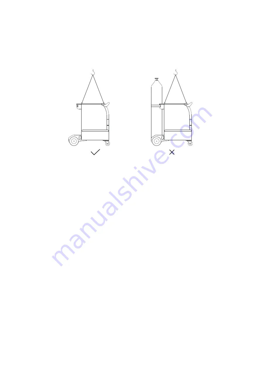
equipments should be unloaded from the power supply first. When moving the 
power source on the ground, it is necessary to fix the cylinder with a strap or chain 
to prevent dumping and injuring people.

If the wire feeder is hoisted by lifting lugs for welding, it is necessary to ensure that
it is firm and insulated.

7

Summary of Contents for GRAND MIG 400 PULSE

Page 1: ...600 PULSE IMPORTANT Read this OPERATOR MANUAL together with PRESCRIPTION AND COMPLIANCE MANUAL before to use this equipment In case of loss one of two parts contact immediately your dealer Allow the o...

Page 2: ...7 4 4 Welding Operation 49 5 TIG Welding 56 5 1 Accessories 56 5 2 Welding Operation 56 6 STICK MMA Welding 57 6 1 Accessories 57 Welding Operation 59 7 Arc Gouging Welding 60 7 1 Installation Instruc...

Page 3: ......

Page 4: ...power source Installation inspection and repair of power source must be carried out by electricians and temporary construction points should be connected by electricians Supervisors shall be provided...

Page 5: ...of electric shock Turn o all input power when transferring work place replacing fuse repairing or not using the equipment Beware of welding fume and harmful gases When welding steel plates with coati...

Page 6: ...h Electrical Base Field May be Dangerous Those who use cardiac pacemakers shall not approach the power source in use and welding workplaces without the permission of a physician It is strictly forbidd...

Page 7: ...iece must be well connected with the ground clamp Users should be responsible for the interference caused by welding Noise Produced during Welding can Easily Cause Hearing Loss In order to avoid the h...

Page 8: ...t When moving the power source on the ground it is necessary to x the cylinder with a strap or chain to prevent dumping and injuring people If the wire feeder is hoisted by lifting lugs for welding it...

Page 9: ...00 PULSE Power supply 3 phase 380V 460V 15 10 3 phase 380V 460V 15 10 Rated input current A 27A 380V 27A 460V 38A 380V 31 5A 460V Frequency Hz 50 60 50 60 Rated power 17 5 KVA 25 KVA No load voltage w...

Page 10: ...tput voltage V 20 8 44 Gouging output voltage V 24 8 44 Protection class IP23 Insulation class H EMC class A Weight kg 56 Dimensions L W H 770 340 505 Wire Feeder Type GRAND FEEDER PULSE Power supply...

Page 11: ...Water Cooler Unit Type GRAND COOLER PULSE Power supply 380V 1 50 60Hz Q max 8L min pump H max 15m Rated input current 0 5A Protection class IP23 Weight kg 30 Dimensions L W H 658 360 260mm 10...

Page 12: ...to set and operate the power source Front Back Panel of Power Source No Description No Description 1 Crane eyelets 8 CO2 heater supply socket 2 Handle 9 Power supply cable 3 Control panel 10 Serial po...

Page 13: ...e feeder unit is connected press or turning any of the knob or button on the wire feeder panel the power source turns into MIG MAG mode Selection button for electrode type Press it to select the type...

Page 14: ...wer source front panel will light on And the main relay of the power source would turn o The fan cool LED When the led lights on the fan keeps working under manual mode When the LEDs are o the fan sta...

Page 15: ...slot and the housing kit for water cooler rack The cooling agent is lled through coolant lling No Description 1 Fast socket for water blue 2 Fast socket for water red 3 Coolant lling 4 Handle 5 Coola...

Page 16: ...mp for connection hose package CHP 4 Euro connector 5 Remote control output connector 6 Carriage welding tractor connector 7 Fast socket for water blue 8 Fast socket for water red 9 Gas in connector 1...

Page 17: ...eder Icon Name Description Left display Display the current voltage and so on Right display Left knob Used to regulate welding parameters such as current voltage and so on Right knob JOB adjusting but...

Page 18: ...t display shows preset voltage when the indicator light is on Arc length indicator The right display shows arc length when the indicator light is on Manual mode indicator The indicator light is on whe...

Page 19: ...hickness when the indicator light is on Inductance indicator The right display shows inductance when the indicator light is on Side Panel of Wire Feeder inside Press the MIG MAG torch switch the MIG M...

Page 20: ...MAG welding Double pulse MIG MAG welding Welding cycle selection button Press the button select the four types cycle 2T Operating mode 2 cycles is provided for short manual welds 1st cycles Press torc...

Page 21: ...lve for shielding gas opens the gas ow Weld voltage is applied on wire electrode 2nd cycles Release torch button Wire feed starts with reduced speed and arc ignites 3rd cycles Press torch button again...

Page 22: ...on again Change from set parameter to stop parameter via a time function Down Slope Continue welding 4th cycles Release torch button again Wire feed stops Weld voltage is switched o after expiration o...

Page 23: ...o manual selection button of carriage welding tractor Manual start stop command button for carriage welding tractor Test button of protection gas inch gas button 2 4 Function Description 2 4 1 Standby...

Page 24: ...stops when standby Auto mode Push switch 1 to OFF position The fan would work when the temperature is over 40 2 4 4 Alarms Function The power sources are completed with a monitoring system of the mac...

Page 25: ...ing liquid circulation is constantly controlled The cooling unit works only when MIG MAG processes is activated After welding the water cooler unit will continue to work for 180s The cooling unit pump...

Page 26: ...adjust higher power output causing damages on the existing supply network or can choose the cable at maximum output current 2 4 6 Protection from Inverter Failure The bus voltage has a feedback to th...

Page 27: ...nel of wire feeder to test the gas Push it again the gas stops 2 4 9 Display Turning knob display shows set max current at no load after 1 5s shows the attenuation by the remote control if connected I...

Page 28: ...lding current t3 t4 When releasing the torch button the controller automatically stops the welding process the current goes to zero and the machine continue to exhale for some time post gas time The p...

Page 29: ...nt t2 t3 When pressing the torch button in second time the controller automatically stops the welding process the current becomes to zero and the machine continue to exhale for some time post gas time...

Page 30: ...ion Up slope time t5 t7 The current goes to the stop current when pressing the torch button with time function Down slope time t7 t8 When releasing the torch button the controller automatically stops...

Page 31: ...3 0s 0 3 Downslope time 0 1s 3 0s 0 3 Stop Current 20 80 50 Post gas time 0 5s 10s 5 0 The display shows Auto that means the post gas time is set automatically in synergy with the value of current and...

Page 32: ...rocess after expiration of the de ned time like the case2 and case3 in the gure the current goes to zero and the machine continue to exhale for some time post gas time The pre gas time and post gas ti...

Page 33: ...arc becomes too long the current slows down 2 4 15 Hot Start Add current to the welding current at striking of the arc in order to warm up the beginning of the welding This added current has a value...

Page 34: ...and arc force are joined together by AF For GRAND MIG PULSE series the range of AF is 0 250 When calculated current becomes higher than the maximum of machine the maximum current limit is used AF has...

Page 35: ...nt 20 80 Only for 4S cycle When the welding mode F02 is 1 2 3 or 4 it is e ective F09 Arc stop time 0 5 s Only for robot system When the welding mode F02 is 1 2 3 or 4 it is e ective F010 Welding curr...

Page 36: ...4 it is e ective F019 Level 30 90 When the welding mode F02 is 4 it is e ective F020 Welding time 0 1 25 s Only for spot cycle F021 Pre gas time 0 1 5 0 s Set the pre gas time When the welding mode F0...

Page 37: ...ce level and preset current because the energy in the area A equals area B Description for PRG You can set the PRG by the remote control unit Each PRG number can store 50 sets of data The PRG can stor...

Page 38: ...4 ALSI5 1 2 70 30 Ar He 25 ALSI5 1 6 100 Ar 26 ALSI5 1 6 70 30 Ar He 27 ALMG5 1 0 100 Ar 28 ALMG5 1 0 70 30 Ar He 29 ALMG5 1 2 100 Ar 30 ALMG5 1 2 70 30 Ar He 31 ALMG5 1 6 100 Ar 32 ALMG5 1 6 70 30 Ar...

Page 39: ...and the other one is use to adjust voltage Synergic mode a knob is use to adjust the current and the other one is use to adjust inductance The STICK MMA welding arc gouging welding and TIG welding can...

Page 40: ...use please read the warning label on the welding power source carefully Do not cover smear or tear the label Serial number generally pasted on the back panel or bottom of the machine The serial numbe...

Page 41: ...are shown in the tables below Model Accessories Amount PCS Marks GRAND MIG 400 PULSE GRAND MIG 500 PULSE GRAND MIG 600 PULSE Power source 1 Trolley 1 Water cooler slot 1 House kit for Water cooler slo...

Page 42: ...source the installation of air cooling con guration can refer to the corresponding steps the assembly diagram is shown below The water cooler unit consists of two kits housing kit for water cooler slo...

Page 43: ...rews in the back side of housing kit for water cooler slot and take o the back panel 2 Remove the gas meter and connection hose package in the housing kit for water cooler slot 3 Put the housing kit f...

Page 44: ...housing kit 7 Remove the plastics cover on the top of the housing kit and take out the terminal from the hole 8 Connect the 3 ground wires of the housing kit to the side cover then close the side cove...

Page 45: ...short connect terminal 12 Connect the two terminals of the power source and housing kit This operation requires three people to cooperate two of them to lift the power source the other one to connect...

Page 46: ...cording to users requirement the gas cylinder support could be selected and installed to the power source And the gas cylinder could be placed here and tighten by chain 4 2 3 Install Wire Feeder The w...

Page 47: ...Assembly Steps with wheel 1 Fix the wheels and torch holder optional and than x the wire feeder to the power source M5 12m M6 14m M6 14m Install torch holder 46...

Page 48: ...cooler unit should be short connected with a bridge pipe And the fast sockets on the wire feeder back panel are not connected When it is connected with the water cool CHP the blue and red fast socket...

Page 49: ...peed and the other one is use to adjust voltage Synergic mode a knob is use to adjust the current and the other one is use to adjust inductance When the wire feeder is connected with the gas cool torc...

Page 50: ...back panel Step 2 Connect the blue fast socket with bridge pipe Step 3 Switch on the machine Step 4 Press the torch switch the water ow cycle test should be active in 15s And the cooling liquid shoul...

Page 51: ...e Service Center Gas Check Step 1 Turn on the knob of the gas cylinder and turn the gas ow adjusting knob in anticlockwise direction Step 2 Press the button on the control panel of wire feeder to test...

Page 52: ...92 Ar 8 CO2 1 2 1 6mm V Stainless steel 98 Ar 2 CO2 1 0 1 2mm V Flux self shielded 1 0 1 2mm K Flux gas shielded 100 CO2 75 80 Ar 25 20 CO2 1 0 1 2mm K Aluminum Al 100 Ar 0 8 1 0mm U 1 0 1 2mm U 1 2...

Page 53: ...scale Check if the pressure is suitable Pressure too weak wire slips Pressure too strong cause wear and tear Set the pressure Plastic tube Check if there is dust in the tube or around the wire feedin...

Page 54: ...f left movable cover If the power source work with the robot the setting of welding parameters can be seen in the manual of the supporting equipment of the robot Step 1 Select welding mode by pushing...

Page 55: ...he larger the number the harder the arc that is the greater the sti ness 4 After setting up welding can be carried out Mode 2 Setting parameters through JOB the speci c operation is as follows If So U...

Page 56: ...ration the machine can begin to work Con gured JOB JOB 0 1 Select the con gured JOB number by and of the front panel of the wire feeder If you need to view the parameter values in JOB or create a new...

Page 57: ...nd con rm they are in normal condition Step 1 Connect the power plug to the socket You must ground the earth wire in the power supply cable Step 2 Turn on the main switch Step 3 Select the TIG mode by...

Page 58: ...10m extension cable male female 1 1 standard optional Note The remote control is standard equipped with 5m connection cable male male And optional extension cables of two length 5m or 10m Correct Sche...

Page 59: ...Wrong Schematic Diagram Variant A with four feet Variant B with two feet Variant C without feet Variant D without feet without magnet 4 screws 4 feet 1 sheet 1 magnet 1 RC101 58...

Page 60: ...ing manual and synergy mode Manual mode Turn the main knob to set the value of current hot start and arc force based on the type and diameter of the electrode thickness of workpiece and the welding po...

Page 61: ...connected with one knob remote control device to set welding current 7 3 Welding Operation NOTE Before welding operation the operators should inspect the equipment components and con rm they are in n...

Page 62: ...clamp is 80 100mm Step 4 Set the current according to the diameter of the electrode thickness of workpiece and welding position Take the following list as suggestion Thickness of workpiece mm 4 6 6 8...

Page 63: ...re source and welding spatter can be found around the environment where the power source is placed The ambient temperature are as follows During operation 10 to 40 Storage and transport 25 to 55 with...

Page 64: ...y Arc striking is di cult and easy to pause a Make sure quality of tungsten electrode is high b If the electrode is not dried it will cause unstable arc welding defect increases and the quality is dow...

Page 65: ...the loosing joints In case of oxidation remove oxide lm with sand paper and connect again d Prevent water from entering into the machine and prevent the machine from getting moist If any blow and dry...

Page 66: ...inside the machine 1 Check why the supply voltage is outside the limits 2 Shut o and switch on the machine if the alarm comes again please ask to the Service Center HI AC Err 12 The supply voltage is...

Page 67: ...oken 2 Loose gate wirings of the power transistor Shut o and switch on the machine if the alarm comes again please ask to the Service Center ALL Err 21 During normal operation the output voltage is mi...

Page 68: ...Err 26 Alarm o set hall sensor 1 The current sensor output has wrong data 1 Check the hall sensor power supply 2 Replace the main control board ALL Err 27 Power transistor test failure At start up th...

Page 69: ...with water cooling system missing bridge wire in the water cooling connector 2 Water missing or non circulating one of the two exit of water is open water lter ll of dust pump stacked for long time i...

Page 70: ...n knob in the front panel shut o the machine and turn on again 3 Download again the software replace the main board T178 Err MEM Err 51 Alarm during the reading of the memory Appear when it is not pos...

Page 71: ...rr 63 Output voltage lower than expected 1 Check the connections to the external wire feeder 2 Wrong calibration of the output voltage Try to download the default calibration 3 Failure in the main boa...

Page 72: ...charge alarm 4 Power transistor broken 5 Electrolytic capacitors broken 6 Missing connection of the DC BUS to the inverter board Auxiliary connection between inverter board and interface board not we...

Page 73: ...nnecting cable check these parts 2 If the real voltage displayed in the instrument during the welding don t change there are problems in the ground cable or in the torch control both 3 Check if the wo...

Page 74: ...the torch or inside the torch Gas nozzle must be cleaned or changed 4 Gas valve is not working Check the gas used according to the problem selection in the side panel of the wire feeder 5 Check leakag...

Page 75: ...d program in the side panel 2 Torch problems control the state of the liner and the tip 3 Bad condition of connections control the state of the torch connection interconnecting cable 4 Control circuit...

Page 76: ...1 F S 2 F S 3 FS4 FS5 lterboard 10 9 OUT OUT positive negative p o s iti v e n eg at iv e RED ORANGE VIOLET BLACK temp current temp current temp current temp current G1 G2 G1 G2 G 1 G 2 G 1 G 2 1 2 3...

Page 77: ...4 5 5hole 1 2 3 4 5 6 7 8 J1 1 2 3 4 5 6 7 8 9 1 0 J2 1 2 3 3 hole 1 2 switch 1 2 3 4 softwaredownloadboard J3 OUTPUT T25 3 5 4 3 2 1 5 4 3 2 1 J02 5 4 3 2 1 6 2 8 8 9 1 0 1 1 1 2 1 3 6 7 28 9 1 0 11...

Page 78: ...Circuit Diagram of Water Cooler Unit 5 6 1 2 4 3 2 3 Flow switch 1 2 3 FAN Filter heat exchange Blue Red switch Tank PUMP Optional Fan Pump Switch Heat exchange 77...

Page 79: ......

Page 80: ...LOKERMANN Srl Via Produzione 16 18 37044 Cologna Veneta VR Italy Tel 39 0442 1722469 lokermann lokermann eu www lokermann eu...

Reviews: