Crimp the
Chassis Connector
onto the black wire. Your
Chassis Connector
may be a non-insulated #8
ring terminal, female quick disconnect terminal, or other connector you chose for your chassis ground
connection earlier.
Crimp insulated #10 ring terminal, insulated female quick disconnect terminal, or other connector you
chose for your
Power Connector
onto the red wire.
Follow the next step(s) based on the positive or negative chassis polarity noted earlier:
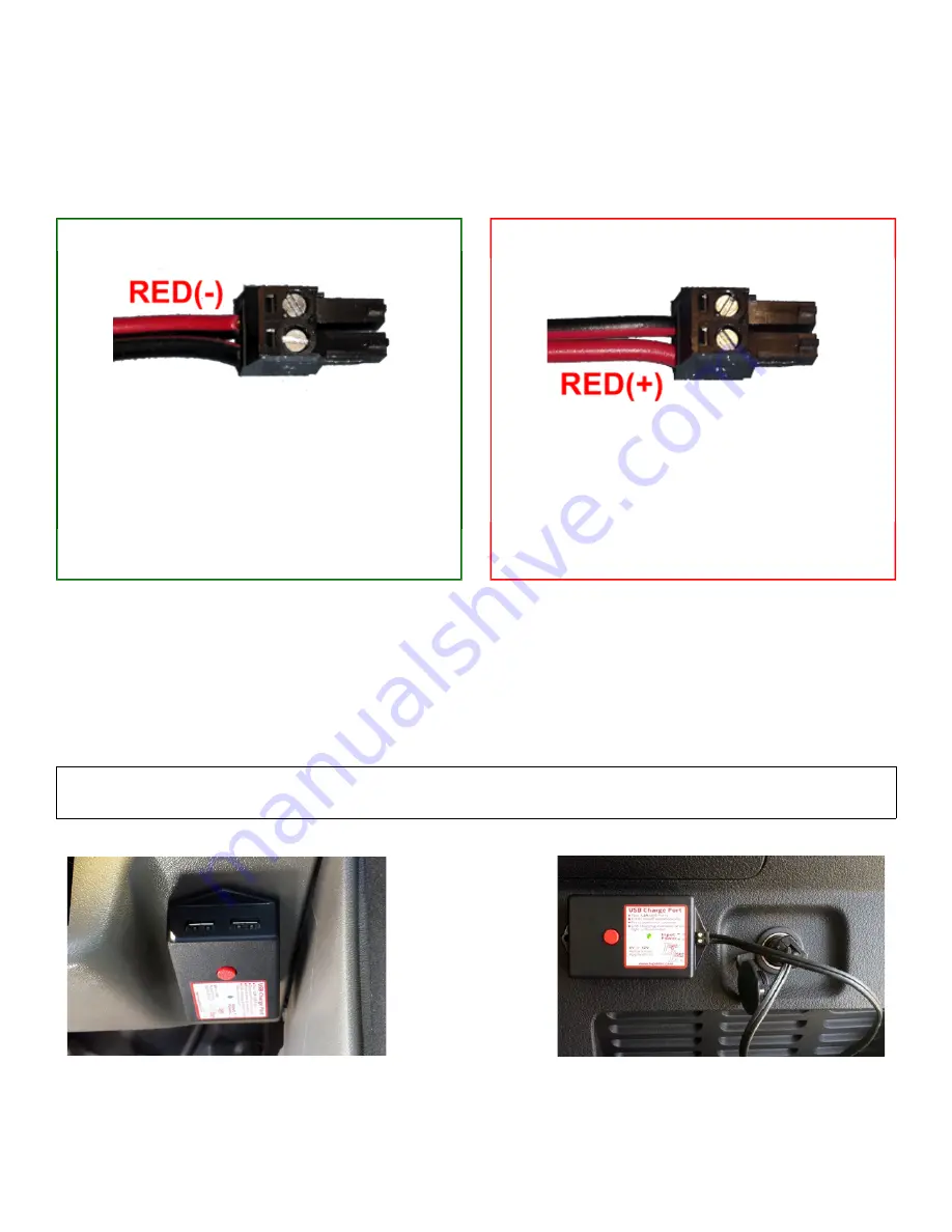
Positive Chassis
Looking into the connector’s wire holes with
the screw heads up, insert stripped end of red
wire into left hole of power connector and
tighten the screw to hold the wire snugly.
Repeat for the black wire into the other (right)
hole of the power connector.
Negative Chassis
Looking into the connector’s wire holes with
the screw heads up, insert stripped end of black
wire into left hole of power connector and
tighten the screw to hold the wire snugly.
Repeat for the red wire into the other (right)
hole of the power connector.
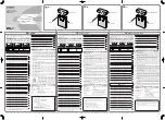
Fully insert
Input Connector
into USB Charge Port.
Connect the
Chassis Connector
to the vehicle chassis ground point chosen earlier. If you use the #8 non-
insulated ring terminal, insert the #8 screw through the #8 tooth washer and the ring terminal, and use the
hex key to screw it into the hole you drilled earlier.
Connect the
Power Connector
to the terminal, stud, screw, or other power source point chosen earlier.
Insert 3 Amp ATO fuse into the fuse holder.
Double check that all wires are connected safely and correctly.
Tip – Use tie wraps or other means to support the wires to prevent them from damage or interference with vehicle
moving parts or systems.
Reconnect vehicle battery.


