background image

 
Logic IO ApS.  


Ph:   (+45) 7625 0210 

Holmboes Allé 14                         


Fax: (+45) 7625 0211 

8700 Horsens                               


Email: [email protected] 

Denmark                                       


www.logicio.com / www.rtcu.dk  


Technical Manual 1.00, PNM-200 Series V1 


Page 16 of 19 


Appendix A – Mounting the dashboard bracket 

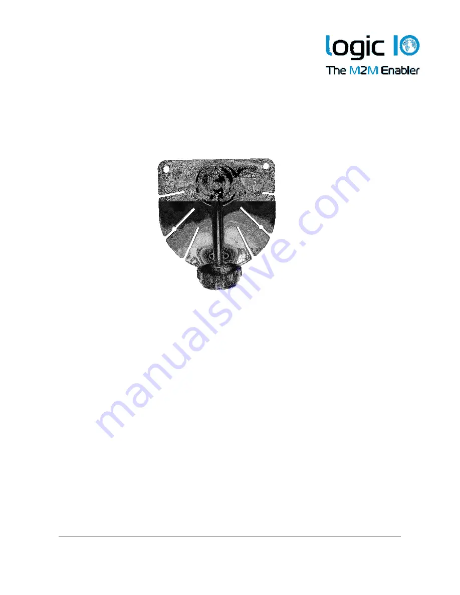
A dashboard mounting bracket is included for easy installation of the PNM-200 series 
device. In the following the mounting of the bracket will be described. 


1.  Loosen the adjustment screw handle, and  set the bracket arm to an upraised 

position 


2.  Loosen the securing screw until there is a gap between the bracket part and the 

metal plate. 


3.  Place the metal part on top of the bracket at the starting point of the mounting jack 

on the back side of the PNM device. Slide the bracket part until it is at the desired 
position. Fasten the securing screw. Please note the orientation of the bracket 


Bracket  

Adjustment 
screw handle 

Summary of Contents for PNM-200

Page 1: ...Technical Manual 1 00 PNM 200 Series V1 Technical Manual for the PNM 200 series Version 1 00...

Page 2: ...es also offers support for connecting up to two cameras used for rear view or cabin view etc The PNM 200 series comes with the PNM software maps pre installed and interface cables for the RTCU MX2i pr...

Page 3: ...aphical view 4 Package overview 5 PNM 200 Series Overview 6 Typical System Connection 8 PNM interface box 8 External connections 8 Typical Application 10 Interfacing to the RTCU MX2i Pro Pro 10 Interf...

Page 4: ...ogic IO ApS Ph 45 7625 0210 Holmboes All 14 Fax 45 7625 0211 8700 Horsens Email info logicio com Denmark www logicio com www rtcu dk Technical Manual 1 00 PNM 200 Series V1 Page 4 of 19 Graphical view...

Page 5: ...ra support 1 Mounting Bracket PNM 200 series device mounting bracket 1 PNM interface box Interface box to the PNM 200 series device 1 8 GB SD CARD With pre installed software Typically already install...

Page 6: ...ower by the application SET User defined key Key 1 User defined key Key 2 User defined key Key 3 User defined key Key 4 User defined key Led s Status LED s Touch Screen To interact with the applicatio...

Page 7: ...SD card compartment Cover The cover for the compartment where the SD card reader is located The PNM 200 series device can be reset asynchronously using the reset button located at the backside of the...

Page 8: ...includes communication power regulation protection and control circuit of the PNM device In the following sections the external connections to the device interface will be described External connectio...

Page 9: ...the box is polarized wrong while the connected RTCU unit is correct polarized and power is applied the internal GND connection will break For avoidance of such a scenario a fuse can be installed on t...

Page 10: ...face box The PNM interface box is supplied from an external DC supply using the power cable An example of connection to RTCU MX2i pro is shown in the drawing below 1 Connect the PNM device interface c...

Page 11: ...directly through the digital output 2 of the RTCU CX1 An example of a connection to the RTCU CX1 pro is shown in the drawing below The flying lead cable is color coded and these colors will be used i...

Page 12: ...additional information on the interface cable 3 Enable the PNM interface from the RTCU CX1 through the user application Note that the power to the PNM device is controlled by the RTCU CX1 The module w...

Page 13: ...ers connection for up to two analog cameras using the BNC connector available at the PNM device interface cable Analog camera 1 must be connected to the cable labeled with BNC 1 and analog camera 2 mu...

Page 14: ...om the PNM device to the PNM interface box 2 Connect the PNM device interface to one of the available serial ports on the PC with the PNM 200 series PC interface cable 3 Connect the power supply to th...

Page 15: ...software and maps are pre installed on the delivered SD card C 70 20 Storage temperature Operating humidity non condensing 80 10 MIL STD 810F Method 514 5 Table 514 5C VII Figure 51 45C 1 g 20 operat...

Page 16: ...n the following the mounting of the bracket will be described 1 Loosen the adjustment screw handle and set the bracket arm to an upraised position 2 Loosen the securing screw until there is a gap betw...

Page 17: ...age 17 of 19 4 The vertical angle and rotation of the PNM device can be adjusted using the screw handle on the bracket 5 Remove the protection paper of the adhesive and place the bracket on a proper l...

Page 18: ...reader is hidden in a compartment for protection purpose Access the compartment with the SD CARD reader as follows 1 Unscrew the two M2 screw from the compartment cover 2 Pull up the cover slightly u...

Page 19: ...200 Series V1 Page 19 of 19 A side view of the terminal when the cover is removed is as follows Interface Description Mini USB Port Mini USB 2 0 service port USB Port USB host port Earphone jack Conn...

Reviews: