Digital Door Lock - How to Change the Code (M-Series)
NOTE: Never oil lock or remove silver screws. This will void warranty!
Failure to follow the instructions could result in damage to your lock, so please read carefully.
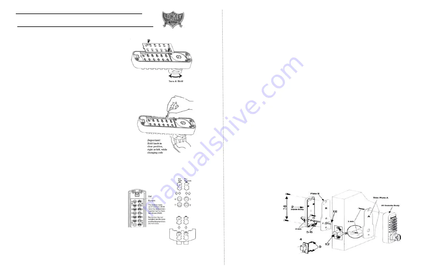
1. Hold the outside body in the horizontal position. Remove the 2 red screws
with a #2 screwdriver. Carefully remove the plate, as there are many springs
attached to it.
2. Important: You must turn the knob to the clear position and hold in that
position until you have completed the code change. By not holding the knob
in the clear position, you could damage the lock and void the warranty.
3. There are BLUE (non-code) and RED (code) tumblers. Your code is made
up of red tumblers always prefixed by turning the knob to clear.
While continuing to hold the knob in clear position, use tweezers to lift out
code/non-code tumblers you wish to change.
Important: Hold knob in clear position, right or left, while changing code.
4. Replacing code and non-code tumblers.
While holding knob in clear position, make sure the blue or red colored end of the
tumbler is facing upwards. Make sure notch is facing proper direction. See Fig. 3.
IMPORTANT: It is imperative that the tumblers are inserted with the red or blue
color side up and knob is turned in the clear position.
Using the tumblers provided, you can change your code from a 2-digit code to a
5-digit code.
If more red or blue tumblers are needed, you can request a tumbler kit by sending $4.00 to
Lockey Systems, PO Box 543, Mt. Pleasant, MI 48804. You will be sent 2 Red and 4 Blue tumblers.
To
increase
the code, remove the blue tumblers and replace with red
tumblers.
To
decrease
the code, remove red tumblers and replace with blue
tumblers.
5. When you have completed changing the code, carefully replace
cover, making sure all springs are in place. Replace 2 red screws. Turn
knob to clear and test code.
Always test your new code before installing and always test on door
before locking!
M-210-EZ MOUNT Instructions
Using the EZ Mount Plate
EZ Install only if you have the EZ Mounting Plate
1. After determining the handing of your lock and setting the secret code, you are now ready to install
your lock to the EZ Plate.
2. Place the outside body #1 to plate “A” and screw into place using the two- 5mm x ½” screws.
3. Place the brass guide pin (#15) into PLATE “B”. It screws into the hole on either side of the large hole
in trim plate “B”.
4. Install adjustable deadbolt (#12) into door to the desired length; either 2 3/8” or 2 ¾”. (See Fig. 3 Front
Page)
5. Place trim plate “A” with outside body to the outside of door. Place plate “B” to the inside of door and
make sure guide pin (#15) fits into the small hole in the deadbolt. Hold tight to door and screw into place
using the two- 4 mm. x 5/8” or 4 mm. x 1 ¼” screws depending on the thickness of the door.
6. Place the correct length spindle (#5 or # 6) into the large hole on trim plate “B”. (See IV d. Front Page)
The spindle should go all the way to the outside body (#1) and should have about ½” of the spindle
sticking out of plate “B”. The spindle MUST be placed on the same angle as the angled slot in the
deadbolt.
NOTE: If you have more that 7/8” of the spindle sticking out, your spindle is too long and will bind your
lock. You must use the shorter spindle or cut down to ½”.
7. Place inside body ( #2) to the trim plate “B” and screw into place using the 2 - 4mm. x 3/8” screws.
8. Your lock is now ready to test before you close your door. From the inside you should be able to lock
and unlock your deadbolt. From the outside (combination side), turn your lock to the locked position.
Now enter your secret code and your lock should unlock the deadbolt.
NOTE: If you need to use your secret code to lock the door, and no code to unlock the door, your
handing is set up wrong. Simply change the handing on your outside body, referring to item # II in
your installation instructions section.
Fig. 1
Fig. 2
Fig. 3
Summary of Contents for M-210 DEADBOLT
Page 1: ......


