background image

6  ELECTRICAL INSTALLATION

30

CODE

DESCRIPTION

JP10

6-pole flame controller connector

JP12

Fumes sensor or generator fin sensor input

JTAG

S61 controller programming connector

MAIN 230V (L, N)

S61 controller power 230 V AC

N.O. contact

Pump contact, N.O.

P7 (R, W, Y, o)

Consent inputs 

P8 (GND, L, H)

CAN BUS connector

PUMP 230V (L, N)

Hydraulic pump power output

SPI

Communication port with Mod10 controller

SRT1

Hydraulic pump rotation sensor input

SRT2

Hot water flowmeter input

TA

Ambient temperature probe input

TA1

Input probe of evaporator output

TA2

Not used

TCN

Combustive air temperature probe input

TF

Exhausted gas thermostat input

TG

Generator temperature probe input

THMF

Hot water delivery temperature probe input

THRF

Hot water return temperature probe input

TL

Generator limit thermostat input

SCH S61

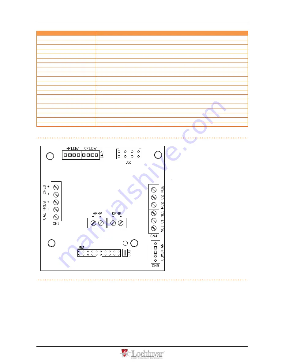
Figure 6�2 – Mod10 controller

Mod10 controller

LEGEND

HFLOW 

  Not used

CFLOW 

  Condensation water sensor control

J51 

  SPI connector

HPMP 

  Primary circuit hot water pump control 

output (0-10 V)

CPMP 

 Low consumption fan control output 

(0-10V)

NC1-C1 

  Status indication of locking warnig/error

CN5 

  Blower control

J82 

  W10 auxiliary controller connector

J83 

  W10 cable shielding connection W10

CN1 

  Inputs 0-10V (not used)

Summary of Contents for LCGHP

Page 1: ...Installation user and maintenance manual LCGHP LSGHP powered by gas and renewable energies Air Water gas absorption heat pump...

Page 2: ...f this manual other than for personal consultation must be previously authorised by Lochinvar The rights of those who have legitimately filed the registered trademarks contained within this publicatio...

Page 3: ...0 5 1 GENERAL INSTALLATION PRINCIPLES 20 5 2 POSITION OF THE APPLIANCE 20 5 3 HYDRAULIC CONNECTIONS 22 5 4 GAS SUPPLY 24 5 5 CONDENSATE DISCHARGE 24 5 6 FILLING OF HYDRAULIC CIRCUIT 25 5 7 EXHAUST FLU...

Page 4: ...nformation for a particular country References If the appliance is connected to a Comfort Control Panel see detail CCP in Figure 6 3 p 31 it is switched on and controlled by the Comfort Control Panel...

Page 5: ...id or near the appliance problems with the electrical gas grid or hydraulic circuit parts of the appliance submerged in water or otherwise damaged controls or safety components bypassed or defective I...

Page 6: ...only be done by a contractor legally author ised to work on gas appliances and equipment Use only original spare parts 2 1 WARRANTY TERMS Warranty can be invalidated by each one of the following cond...

Page 7: ...and complete Installation of the appliance may only be carried out by professionally qualified personnel by i e firms qualified according to the cur rent legislation of the country of installation Pr...

Page 8: ...sistance Proper ordinary maintenance ensures the efficiency and good operation of the appliance over time Carry out maintenance operations according to the instructions supplied by the manufacturer Fo...

Page 9: ...C with manual reset Sealed circuit safety relief valve Safety by pass valve between high and low pressure parts of the sealed circuit Antifreeze functions for hydraulic circuit Ionization flame contr...

Page 10: ...r operating conditions other than nominal refer to the Design Manual 2 For flow rates different from the nominal refer to the Design Manual 3 PCI 34 02 MJ m3 1013 mbar 15 C 4 PCI 46 34 MJ kg 1013 mbar...

Page 11: ...n bar 4 Maximum flow flue condensate l h 4 Water content inside the apparatus l 4 Water fitting TYPE F thread G 1 1 4 Gas fitting TYPE F thread G 3 4 Fume outlet Diameter mm 80 Residual head Pa 80 Siz...

Page 12: ...1 5 Evaporator l 3 7 Cooling volume transformer l 4 5 Cooling absorber solution l 6 3 Solution pump l 3 3 TEST PRESSURE IN AIR bar g 55 MAXIMUM PRESSURE OFTHE COOLING CIRCUIT bar g 32 FILLING RATIO kg...

Page 13: ...intenance manual LCGHP LSGHP 13 Figure 3 2 Dimensions LCGHP low consumption ventilation Front and side views dimensions in mm Figure 3 3 Service plate A B Hydraulic gas unions detail LEGEND G Gas fitt...

Page 14: ...ol of the appliance will occur exclusively by operating the DDC In this case refer to the manual supplied with it The appliance must never normally be switched on and off by shutting off the power sup...

Page 15: ...interval the appliance automatically launches the start up procedure again If code u_12 is signalled 4 times on successive activation attempts the code persists the appliance locks out the flame contr...

Page 16: ...ximately three seconds and then the name of the board S61 ap pears After around 15 seconds after the appliance powers up the appliance starts running if the required consent is available During correc...

Page 17: ...24 Timed forcing to maximum power 2 24 25 Stop power forcing 2 25 E EXIT MENU 2 E The general operating codes of the controller can be reset with functions 20 and 21 Actions 23 24 and 25 are used to...

Page 18: ...fitted to the appliance before proceeding you must acquire this informa tion Paragraph 4 2 p 15 At the moment of installation the appliance is set up by the installation technician for best operation...

Page 19: ...he above recommendation is necessary in order to avoid to fill continuously with water that may imply the additional intro duction of oxygen and the consequent dilution of the used inhibitor for ex gl...

Page 20: ...ctions the right and left sides must have a minimum clearance of 45 cm the minimum rear clearance from walls is 60 cm see Figure 5 2 p 22 No obstruction or overhanging structure roofs eaves balconies...

Page 21: ...any damage arising from failure to observe this warning Installation at ground level If a horizontal support base is unavailable see also SUPPORTS and LEVELLING below it is necessary to create a flat...

Page 22: ...lence is required such as bedrooms meeting rooms etc Evaluate the noise impact of the appliance with respect to the installation site avoid placing the appliance in locations such as cor ners of build...

Page 23: ...for health for the environment and for appliances Several products for water treatment are available on the market Lochinvar does not perform detailed market surveys therefore suggests to contact Comp...

Page 24: ...from 1 5 bar to 0 037 bar 37mbar LPG may cause corrosion piping and fitting materials must be resistant to this corrosion Vertical gas pipes must be equipped with a siphon and provided with a drain f...

Page 25: ...ndensate pump must be installed near to the discharge realized in such a way as to prevent icing of the condensate mixed for example with domestic effluents washing machine dishwasher etc usually alka...

Page 26: ...caused by the use or disposal of glycol antifreeze It is equally important to recall that the use of monoethylene glycol modifies the thermophysical characteristics of the water in the plant and in p...

Page 27: ...SPLAY SHOWS Hot water thermostat control selection 3 160 Hot water setpoint 3 161 Hot water temperature differential 3 162 EXIT MENU 3 E Description of parameters Hot water thermostat control paramete...

Page 28: ...hs Display and knob and How to access the menus and following To set the parameters of menu 3 You will need the appliance on and access to the electrical panel see Display and knob Access menu 3 The d...

Page 29: ...ed by installation that is incorrect or that does not comply with current legislation Figure 6 1 p 29 and Table 6 1 p 29 provide details of input and ouput of the S61 electronic board The auxiliary el...

Page 30: ...Input probe of evaporator output TA2 Not used TCN Combustive air temperature probe input TF Exhausted gas thermostat input TG Generator temperature probe input THMF Hot water delivery temperature pro...

Page 31: ...nts componing the CCP AVS37 Comfort Control Siemens RVS61 System controller and set point CCI Comfort Control Interface PLC Programmable Logic Control AVS75 Expansion Optional components to predict QA...

Page 32: ...6 ELECTRICAL INSTALLATION 32 Figure 6 4 CCI DDC...

Page 33: ...S Gas valve ON indicator lamp GV Gas solenoid valve TC Manual fumes thermostat TL Generator limit thermostat FM Flowmeter CWS Condensation water sensor VD Defrosting valve FAN Fan C Fan condenser not...

Page 34: ...or outlet temperature sensor TK Condensate discharge heating element thermostat MA Terminal block REED Hydraulic pump rotation sensor 6 2 HOW TO CONNECT THE APPLIANCE ELECTRICALLY Before making electr...

Page 35: ...CP refer to the specific manuals supplied with it The appliance and the CCP communicate with each other via a CAN bus network The CAN bus network is characterized by a series of elements appliances or...

Page 36: ...EN 3086A H BLACK L WHITE GND BROWN 450 m TURCK type 530 DeviceNet Mid Cable TURCK type 5711 H BLUE L WHITE GND BLACK 450 m Honeywell SDS 2022 TURCK type 531 H BLACK L WHITE GND BROWN 200 m For total d...

Page 37: ...36 on the figure and on the electronic board below the connector 6 If the appliance is an intermediate node repeat the operations from step 2 to step 5 for the other cables required in this way you w...

Page 38: ...e long enough to allow installing it without kinking 4 Remove the sheath for a length of approximately 70 80 mm taking care not to cut the shielding metallic shield and or alu minium sheet and if pres...

Page 39: ...of cable CAN BUS Figure 6 12 Connection of CCI to CAN BUS network LEGEND CCI Comfort Control Interface P8 Orange connector J21 Jumpers CAN BUS on CCI board A detail of terminal node case 3 wires J21 j...

Page 40: ...6 ELECTRICAL INSTALLATION 40 Figure 6 13 Connection of CCI to 1 appliance LEGEND SCH S61 controller CCI Comfort Control Interface Connection of CCI to 1 appliance...

Page 41: ...CAL INSTALLATION Installation user and maintenance manual LCGHP LSGHP 41 Figure 6 14 Connection of CCI to 3 appliances LEGEND SCH S61 controller CCI Comfort Control Interface Connection of CCI to 3 ap...

Page 42: ...truction for connecting the WILO STRATOS PARA pumps are given below Each WILO pump includes its power cord and signal cable 0 10V both 1 5 m long for connection to the appliance s electrical panel For...

Page 43: ...ng diagram for connection of Wilo variable rate pumps LEGEND IP Bipolar pump power switch F Fuse PM Hot water circulation pump primary circuit Pump signal 0 10V wire colours brown connect to ve white...

Page 44: ...nt only Intermediate nodes are appliances or DDCs that are connected to two other elements The diagram in Figure 6 8 p 36 gives an example of a CAN BUS network 3 appliances are connected to each other...

Page 45: ...tor on the board set the jumpers as shown in detail B of Figure 6 10 p 38 8 After finished with all the above operations close the electrical panel and refit the front panel of the appliance How to co...

Page 46: ...oceed as follows You will need the appliance disconnected from the electricity supply 1 Remove the DDC s back panel by undoing the 4 bolts securing it 2 Cut a suitable length of power cord minimum 2x0...

Page 47: ...ormer The following wiring diagrams show the connection of the DDC to 1 appliance Figure 6 19 p 48 and 2 appliances Figure 6 20 p 49 respectively LEGEND DDC CCI DDC AL supply 4 poles connector 1 clamp...

Page 48: ...one unit LEGEND DDC direct digital control SCH electronic board S61 J1 Jumper CAN BUS in board S61 J21 Jumper CAN BUS in board DDC A terminal nodes connection 3 wires J1 e J21 closed H L GND data sig...

Page 49: ...ure 6 21 p 50 and check that the jumper J10 located at the bottom left of the electronic board above the NO Contact contacts is CLOSED as shown in detail A If the power of the pump is equal to or high...

Page 50: ...ance through a relay If several appliances are connected on the same hydraulic circuit it is always necessary to provide a safety transformer SELV secondary with relevant relay make connections accord...

Page 51: ...iable flow pump WILO STRATOS PARA can also be used In this case for the electrical wiring of the pump please refer to Figure 6 15 p 43 and the relevant paragraph The primary circulation pump s must be...

Page 52: ...onnect the plant water circulation pump For how to connect the system pumps see the section with this title in Paragraph 6 4 p 44 Variable flow pump WILO STRATOS PARA can also be used In this case for...

Page 53: ...ntenance manual LCGHP LSGHP 53 Figure 6 25 Button connection for flame controller reset LEGEND 1 White 2 Grey 3 Orange 4 Green 5 Yellow Black 6 Black 7 Yellow Green Ground 8 Brown 9 Blue 10 Yellow 11...

Page 54: ...per the Declaration of Conformity provided by the installer to the owner The Declaration of Conformity CERTIFIES that the installation is compliant with current regulations This Declaration is a manda...

Page 55: ...the installation technician is authorised to perform such operations and in so doing may invalidate the guarantee of the appliance The appliance is delivered already regulated for the type of gas req...

Page 56: ...analyser corresponds to the data given in the Table 7 3 p 58 at the Delta CO2 between MAX and MIN potentiality line with tolerance of 0 3 0 0 Example G20 gas if at point 4 a content of CO2 equal to 9...

Page 57: ...letion of the shut down cycle When the appliance is off switch off power supply and gas supply ac cording to anti icing settings opening the electrical breaker and closing the gas isolation valve GUID...

Page 58: ...e itself 6 Check that the o ring B is fitted 7 Reassemble the gas valve to the blower with the 4 bolts G taking care that the red silicon hose between the venturi tube and the gas valve see detail F o...

Page 59: ...NCE Installation user and maintenance manual LCGHP LSGHP 59 Figure 7 2 Gas changeover Gas changeover LEGEND A Gas valve B O ring C O ring D Gas nozzle E Fixing screws F Red silicon pipe G Fixing screw...

Page 60: ...ance u 412 FLAME CONTROL UNIT ARREST Failure to ignite burner Reset occurs automatically when the solenoid valve opens again new ignition attempt or if the code persists for 5 minutes E 412 FLAME CONT...

Page 61: ...ng in conditioning mode and the flowmeter of the hot module is closed Reset is automatic and occurs when the condition that generated it ceases to apply u 478 OUTLET HOTWATERTEMPERATURE TOO HIGH Outle...

Page 62: ...empera ture sensor Reset may be performed from the controller or from the S61 board via menu 2 parameter 1 If the code persists or occurs again contact authorisedTechnical Assistance E 491 CONTROLLER...

Page 63: ...rmity with the following EC Directives 2006 42 EC Machinery Directive with subsequent amendments and integrations 2004 108 EC Electromagnetic Compatibility with subsequent amendments and integrations...

Page 64: ...e GA ACF60 00 standard e versioni speciali 2 delle Pompe di Calore a gas ad Assorbimento prodotte da ROBUR S p A serie GAHP GS WS A AR standard e versioni speciali serie GAS HP G W A standard e versio...

Page 65: ...1 des unit s Absorption gaz fabriqu es par la Soci t ROBUR S p A s rie GA ACF60 00 standard et versions sp ciales 2 des Pompes Chaleur Absorption gaz fabriqu es par la soci t ROBUR S p A s rie GAHP G...

Page 66: ...i nieniem z kategorii III MODU H dla Total Quality Assurance numer CE 1370 PED H ROB001 13 ITA Wydane przez BUREAU VERITAS ITALIA S p A Via Miramare 15 20126 Milano Italy Uk ady wyposa one s w zaw r b...

Page 67: ......

Page 68: ...ficiency Water Heaters and Boilers 7 Lombard Way The MXL Centre Banbury Oxon OX16 4TJ T 44 0 1295 269981 F 44 0 1295 271640 sales lochinvar ltd uk www lochinvar ltd uk Revisione A Codice D LBR724 14 M...

Reviews: