


20
L o c h i n v a r
D E S I G N E R
’
S
G U I D E
Lochinvar
secondary pump(s). When piped correctly,
the secondary pump helps to prevent flow
through the boiler(s) when they are not firing.
Use of a primary/secondary system will
eliminate the need for a System or Boiler
Bypass. (Figure 19) depicts one example of
primary/secondary piping.
Water Flow Switch
Due to the low water content (between 1 and 6
gallons) of the Copper Finned Tube heat
exchanger, a flow switch is factory installed as
a low water cutoff device on all models. The
flow switch is installed in the outlet piping of the
boiler and wired into the ignition system. A
minimum of 20 GPM is required to make the
flow switch. Per ASME CSD1 and in most
localities, a flow switch is accepted as a low
water cutoff for boilers requiring forced
circulation. (See CSD1 CW-210) It is prudent to
verify preference with the local code official.
A specially sealed flow switch and conduit are
furnished for outdoor installations.
Low Water Cutoff
If this boiler is installed above radiation level, a
low water cutoff device
must
be installed at
the time of boiler installation (option, available
from factory).
Relief Valve
This boiler is supplied with a pressure relief
valve sized in accordance with
ASME Boiler and
Pressure Vessel Code, Section IV
“Heating Boilers”.
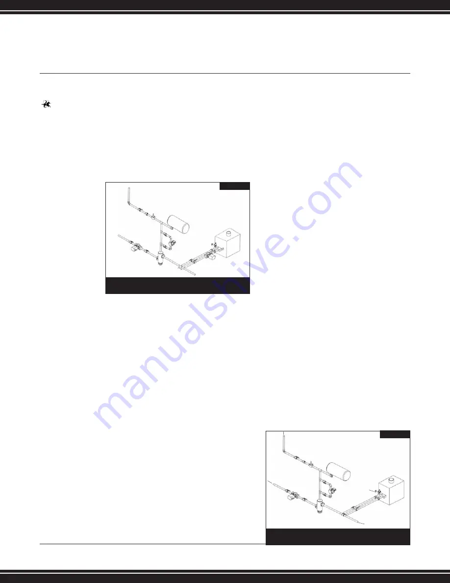
Low Flow Systems
When the system flow rate is less than the
minimum flow required for proper boiler
operation, the boiler should be installed with a
primary/secondary piping system.
This will allow the installation of a secondary-
circulating pump sized specifically to provide a
higher flow rate through the boiler and the
secondary loop piping to ensure proper
operation. See “Primary/Secondary Piping”
for installation and piping requirements.
High Flow Systems
When the flow rate of the system exceeds the
maximum allowable flow rate through the
boiler (Table L), boiler bypass piping should be
installed. The bypass will divert the required
portion of the system flow to the boiler and
bypass excess system flow. This will effectively
reduce boiler flow to an acceptable rate and
increase system flow. The bypass piping should
be sized equal to the system piping. Figure 18
depicts the proper piping arrangement for the
boiler bypass.
(FIG. 20) HIGH FLOW SYSTEM PIPING
HEATING SUPPLY
LOOP
TO FLOOR
DRAIN
MAKE-UP WATER
HEATING RETURN LOOP
LIT0471
IMPORTANT:
Operation
of this boiler
on low
temperature
systems
requires special
piping to insure
correct
operation.
Consult low
temperature
system section
for piping
details.
(FIG. 19) PRIMARY/SECONDARY SYSTEM PIPING
HEATING SUPPLY
LOOP
*12” MAX
TO FLOOR
DRAIN
MAKE-UP WATER
LIT0476
HEATING RETURN LOOP
Summary of Contents for Copper-Fin II CX401
Page 31: ......