21
6 Wiring of S4 Series Sensor
The electric power supply shall be shut off before wiring, so as to avoid electric shock. The
wiring shall be operated strictly in accordance with the wiring diagrams.All modifications
about the circuit units of protector are forbidden!
To access to the PLC, consider the effect of inversion detection impulse.
K1 and K2 is external equipment, choose forced guide safety relay or magnetic contact.
The figure below is the manual reset mode, please connect the light red line (red T) to 24VDC
if need automatic reset.
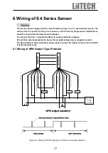
6.1 Wiring of NPN Output Type Protector
Figure 6-1 Wiring of NPN Output Type Protector and output waveform
K1
K2
+
-
24VDC
Power
Supply
K1 K2
emitter
receiver
NPN load
NPN dural output wiring
EDM (Red T)
EDM 2 (Yellow K)
Shield
Shield
0V (Blue GND)
0V (Blue GND)
synchronizing signal line(White CP)
synchronizing signal line(White CP)
24V (Brown VDD)
24V (Brown VDD)
output OSSD1 (Black S1)
output OSSD2 (Green S1)
auxiliary output (Black S2)
Manual reset line (Red T)

