


15
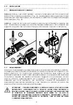
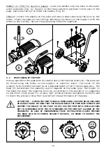
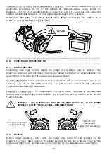
HANDLE «L» TYPE (for electric pumps): screw the handle into the hole on the motor
until possible (Fig. A). Keep it in the final position parallel to the axis of the
pump, and screw the nut to block the handle (fig. B).
TROLLEY: insert the wheels on the axle and secure them inserting the pins in the
holes. Place the pump on the trolley matching the holes on the support with the
holes on the trolley. Secure the pump using the bolts supplied.
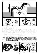
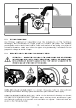
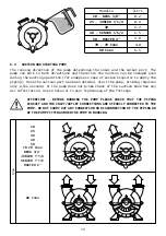
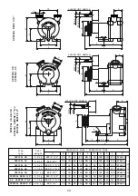
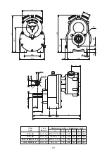
5.2 POSITIONING OF THE PUMP
During operation the pump must be stable and in horizontal position. The pump can
be fixed using the holes on the support or electric motor. The level of the
product to be transferred must be at a maximum depth of 6 m from the pump axis. The
head (H) determines the capacity and it depends on the pump type; the higher is
the head the lower the capacity will be. According to the system it is suggested
to use short inlet pipes for an easy self-priming intake (automatic suction) and
to limit the pressure drop that coud affect the performance of the pump.
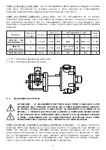
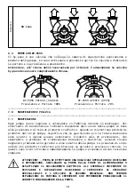
ATTENTION! - FASTEN THE PUMP STEADILY WHEN USING THE PUMP ON AN INCLINED
OR RAISED PLANE. BE SURE THAT THE BASE ON WHICH THE PUMP MUST OPERATE CAN
SUPPORT THE WEIGHT OF THE PUMP. DO NOT USE THE PUMP WITH INSTALLATIONS
NOT IN ACCORDANCE WITH THE CE STANDARDS OR FOR USES NOT ALLOWED BY THE
PRODUCERS. IN CASE OF TRANSFERRING TOXIC OR POLLUTING FLUIDS PREPARE
THE WORK SITE WITH PROPER SECURITY DEVICES, IN ORDER TO PROTECT THE
ENVIRONMENT.
α°
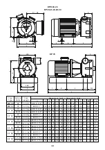
Summary of Contents for EP 20
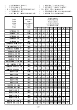
Page 35: ...NAUTIC NAUTIC F ADPE NAUTIC 25 NAUTIC NAUTIC F ADPE 30 40 50 NAUTIC NAUTIC F NAUTIC ADPE 35 ...
Page 36: ...36 MID MID 40 50 MID MASTER 2 ...
Page 37: ...37 POMPA 70 70 Inox 80 Inox POMPA 70 80 ...
Page 38: ...38 LALX LALX 40 50 LALX SENIOR 1 1 2 MASTER 2 ...
Page 39: ...EPH EP NEOS 3 4 EP 30 40 50 EP SENIOR 1 1 2 EP MASTER 2 EP JUNIOR EP EPH EP 20 25 39 ...