29
GB/IE
Make sure that the LED spotlight
2
illuminates the desired area. You
can move the product vertically to adjust the angle.
Make sure the motion sensor
1
covers the desired area. The motion
sensor
1
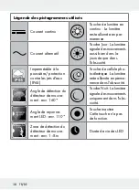
has a maximum coverage range of 8 m, with a coverage
angle of about 160 ° (depending on the mounting height – a height
of 1.80–2.50 m is ideal).
Make sure the motion sensor
1
is not illuminated at night by street
lighting. This can influence its functioning.
Don’t adjust the motion sensor
1
onto trees, bushes or locations
where animals could be easily detected. Do not adjust the motion
sensor
1
to fan heaters, air conditioners, pools or other objects with
fast-changing temperatures.
Use the bracket
4
as a pattern to mark the drilling holes onto the
wall. Ensure that there are no cables or wires in this area in the wall.
Drill two holes (Ø 8 mm) and insert the wall plugs
26
. Screw the
bracket
4
with the help of the screws
25
and check the tight fit. If
necessary, isolate 6–8 mm from house conductor terminal
23
. Con-
nect the outer conductor
5
, the neutral conductor
7
and the pro-
tective conductor
6
to the terminal block
24
of a properly installed
junction box (see Fig. C).
Note:
The connection cable type should be H05RN-F 3G 1.0 mm².
Note:
The protective conductor
6
connection is to be used longer
than the other conductors, so that it is the last one to tear off in the
event of a breakage of the product.
The used connection terminal must have at least the following specifi-
cations:
Type of connection terminal: With screws
Number of contacts:
3
Operating voltage:
> 230 V~
Rated current:
>1 A

