background image

page  4

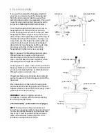
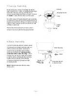
set screw hole

set screw

hanging ball

stop pin

A

B

pin

clip

NOTE:

  The important safety precautions and 

instructions appearing in the manual are not meant 
to cover all possible conditions and situations that 
may occur.  It must be understood that common 
sense and caution are necessary factors in the 
installation and operation of this fan.

5. Fan Assembly.

If you wish to extend the hanging length of 
your fan, you must remove the hanging ball 
from the downrod provided to use with an 
extended downrod (sold separately). [

If you wish 

to use the downrod provided, please proceed to 
instructions following the dotted line below.

]

To remove hanging ball, loosen set screw on 
hanging ball and remove the pin and clip. 
Lower hanging ball and remove stop pin. Slide 
hanging ball off the original downrod, A, and 
slide it down the longer downrod, B (the top of 
the downrod should be noted as having a set 
screw hole; use this hole when setting the set 
screw). Insert stop pin into top of extended 
downrod and raise hanging ball. Be sure stop 
pin aligns with slots on the inside of the 
hanging ball. Tighten set screw securely.

Tip

: To prepare for threading electrical wires 

through downrod, apply a small piece of 
electrical tape to the ends of the electrical 
wires--this will keep the wires together when 
threading them through the downrod.

Loosen yoke set screws and nut at top of motor 
housing.  Remove pin and clip from downrod (if 
you have not already done so). Slide downrod 
through canopy and yoke cover.      

Thread electrical wires through downrod and 
pull extra wire slack from the upper end of the 
downrod.

Place downrod into the motor housing yoke 
and re-insert pin and clip previously removed. 
Tighten yoke set screws and nut securely.  Lower 
yoke cover to motor housing.

WARNING

: Failure to tighten set screw 

completely could result in the fan becoming 
loose and possibly falling.  

["Fan Assembly"  continued on next page.]

downrod

clip

yoke set screw

pin

motor

housing

electrical wiring

canopy

yoke cover

Summary of Contents for ALD52BNK5L

Page 1: ...able of Contents Safety Tips pg 1 Unpacking Your Fan pg 2 Parts Inventory pg 2 Installation Preparation pg 3 Hanging Bracket Installation pg 3 Fan Assembly pgs 4 5 Wiring pg 5 Canopy Assembly pg 6 Bla...

Page 2: ...re is larger than 12 gauge or there is more than one house wire to connect to the corresponding fan lead wires consult an electrician for the proper size wire connectors to use 5 Electrical diagrams a...

Page 3: ...parts inventory that all parts have been included IMPORTANT REMINDER You must use the parts provided with this fan for proper installation and safety w remote d h j k l e a b c g f i a canopy 1 piece...

Page 4: ...from breaker panel and be sure operating light switch is turned to the OFF position WARNING Failure to disconnect power supply prior to installation may result in serious injury Remove existing fixtur...

Page 5: ...t screw hole use this hole when setting the set screw Insert stop pin into top of extended downrod and raise hanging ball Be sure stop pin aligns with slots on the inside of the hanging ball Tighten s...

Page 6: ...ng bracket flat side up and gently push taped wire connectors into outlet box Allow antenna from remote control receiver to hang out of the hanging bracket Modifications not approved by the party resp...

Page 7: ...twice a year blade motor housing blade attachment screws washers blade arm inside motor housing Temporarily raise canopy to hanging bracket to determine which 2 screws in hanging bracket align with sl...

Page 8: ...de of fitter plate Gently push up on glass shade and turn to the RIGHT clockwise until it slides completely into place Refer to diagram 3 Note Pull down VERY GENTLY on glass shade to make sure that gl...

Page 9: ...se or decrease lights If you press button in excess of 0 7 seconds it becomes a dimmer The lights vary cyclically in 8 seconds The light button has an auto resume function which keeps the light at the...

Page 10: ...performance due to a defect in material or workmanship Contact Litex Customer Service at 1 800 527 1292 to arrange for return of fan Return fan shipping prepaid to Litex Industries Ltd We will repair...

Reviews: