10
WWW.LCMETER.COM
LC-ON THE GO
TM
Wireless WiFi Adapter
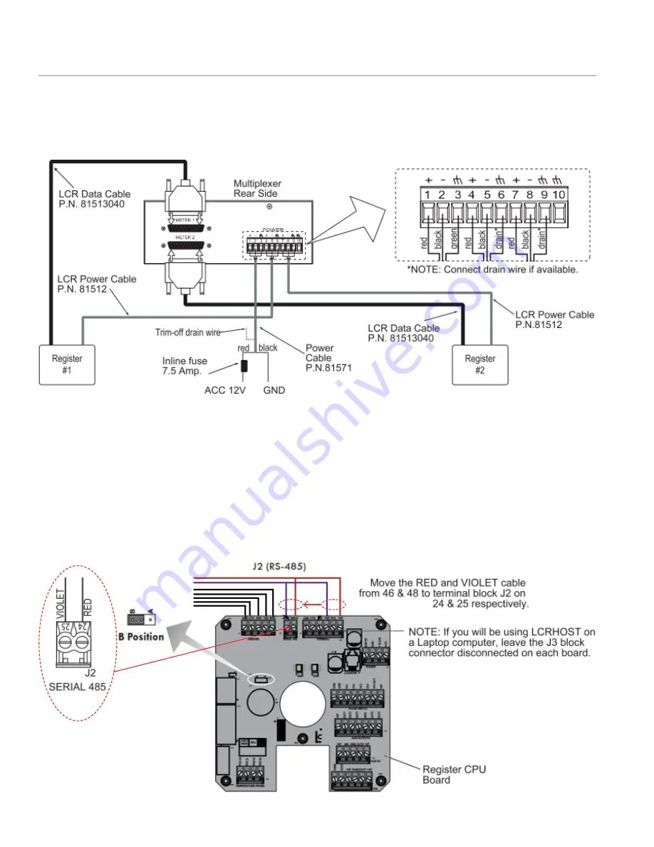
h. Connect Register Data and Power cables. Run
the register’s data and power cables through
split loom, under the vehicle and connect them
to the multiplexer box as shown:
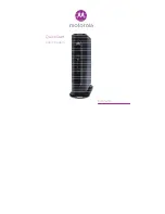
i. Set up the Register’s Communication Protocol
NOTE: Make sure the register is powered OFF before
moving the jumper or the cables.
In order to communicate with a computer device,
the cabling must be modified inside both register
heads.
• Remove the RED and VIOLET cable from terminal
block J3 and wire them into terminal J2.
• Move the RED wire from pin 46 on terminal block
J3 to pin 24 on terminal block J2.
840405
• Move the VIOLET cable from pin 48 on terminal
block J3 to pin 25 on terminal block J2.
• Move the J10 jumper to the B (485) position.
j. The green power light on the ON THE GO
WiFi adapter will illuminate when the system
is powered. A separate power supply is not
required.
Move jumper to B position
for ON THE GO WiFi
IV. CONNECTING TO A NEW DUAL METER SYSTEM


