background image

Connecting additional TMCC products in a “daisy chain”

Y

ou may choose to power additional TMCC products using the same power supply and
Command Base by creating a “daisy chain,” or a series of TMCC units wired in succession.

Refer to Figure 2 and follow these steps as you connect the BPC to the next TMCC product.

When in a daisy chain, the L.E.D. on the BPC will flash for a tenth of a second to
indicate that the BPC is receiving commands for another TMCC product. The L.E.D.
will stay on for half of a second to indicate that the BPC has received a command with
an address it controls. 

Power connections for additional units

1. Attach one wire to the additional Power U terminal on the BPC unit and

connect it to the Power U terminal on another product. 

2. Attach another wire to the additional Power A terminal on the BPC unit

and connect it to the Power A unit on another product. 

3. Add additional products in the same manner, connecting the Power U 

terminals and the Power A terminals. 

COMM connections for additional units

1. Attach the red wire to the DAT terminal of the BPC unit and connect it to

the DAT terminal of the next TMCC product. (Red wire) 

2. Attach the green wire to the COM terminal of your BPC unit and connect it

to the COM terminal of the next product. (Green wire)

3. Add additional products in the same manner, connecting the DAT terminals

and the COM terminals.

Wiring Your Block Power Controller

6

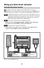
LED

COMMAND

BASE

A/C

POWER

SUPPLY

A

U

Figure 2. TMCC daisy chain connections

Power/A

Common/Ground/U

COMM (Green Wire)

DAT (Red Wire)

Comm Connections

Power Connections

Summary of Contents for 6-14184

Page 1: ...TMCC Block Power Controller BPC 71 4184 250 11 02...

Page 2: ...from the TPC unit to the active section of track Each block of track can be operated in Command or conventional mode with a simple command from your CAB 1 Remote Controller Experience the superiority...

Page 3: ...locks With Two TPC s Wiring a single BPC to two TPC s 9 Controlling four blocks of track with a single BPC 10 Using A Single BPC To Control Two Blocks With Four TPC s Wiring a single BPC to four TPC s...

Page 4: ...BPC unit An isolated power supply not connected to the track will be needed if noise from the TMCC signal interferes with communications This is indicated be a steady green COMM light on the BPC Becau...

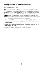
Page 5: ...t to the Command Base with the cable Your BPC is equipped with two additional COM terminals AX and AX At this time leave these terminals empty These are intended for future capabilities Do not wire DA...

Page 6: ...nit and connect it to the Power U terminal on another product 2 Attach another wire to the additional Power A terminal on the BPC unit and connect it to the Power A unit on another product 3 Add addit...

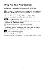
Page 7: ...ID 98 is the factory default setting 1 Remove the jumper from the side of the BPC unit Refer to Figure 3 on page 8 for the location of the jumper 2 Press the ACC button on your CAB 1 Remote Controlle...

Page 8: ...a time Remove the jumper only from the BPC that you are setting Pull the small black connector out from the terminal at the side of the BPC unit Refer to Figure 3 for the location of the jumper 2 Pre...

Page 9: ...ack The L E D illuminates for one half of a second to indicate that the BPC has received a command U A U A B4 2 TPC B2 4 TPC J2 J2 J1 J1 B2 T2 T1 B1 B3 TMCC BPC T1 T2 B2 B1 T3 T4 B1 6 14184 Patent Pen...

Page 10: ...f track between two TPC s Follow these steps to control each block of track 1 Press ACC on the CAB 1 Remote Controller 2 Enter the ID for the block of track you wish to control 3 Press AUX1 to activat...

Page 11: ...on your BPC will control two blocks of track U A U U A U A U A B4 2 TPC B2 4 TPC J2 J2 J1 J1 B2 T2 T1 B1 B3 TMCC BPC T1 T2 B2 B1 T3 T4 B1 6 14184 Patent Pending BLOCK POWER CONTROLLER 4 TPC 2 TPC U A...

Page 12: ...on the CAB 1 Remote Controller 2 Enter the ID for the block of track you wish to control 3 Press AUX1 to activate the numeric keypad 4 Press 1 to power the block of track with the first TPC Press 2 to...

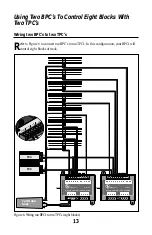
Page 13: ...B2 T2 T1 B1 B3 TMCC BPC T1 T2 B2 B1 T3 T4 B1 6 14184 Patent Pending BLOCK POWER CONTROLLER 4 TPC 2 TPC U A U POWER A AX AX COM DAT COMM B4 2 TPC B2 4 TPC J2 J2 J1 J1 B2 T2 T1 B1 B3 TMCC BPC T1 T2 B2 B...

Page 14: ...etween two TPC s Follow these steps to control each block of track 1 Press ACC on the CAB 1 Remote Controller 2 Enter the ID for the block of track you wish to control 3 Press AUX1 to activate the num...

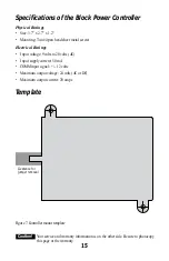
Page 15: ...nput voltage 9 volts to 20 volts AC Input supply current 50 mA COMM input signal 12 volts Maximum output voltage 24 volts AC or DC Maximum output current 20 amps Template Figure 7 Controller mount tem...

Page 16: ...from state to state Instructions for Obtaining Service If service for this Lionel L L C product is required bring the item along with your dated sales receipt and completed warranty information to the...

Reviews: