


UK USERS PLEASE READ THIS
IMPORTANT SAFETY INFORMATION
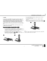
Fuse replacement
This appliance is fitted with a non-rewireable 13 Amp mains plug. The plug contains a
5 Amp fuse. If the fuse has blown it can be replaced as follows:
a) Pull out the red fuse cover/carrier.
b) Remove and dispose of the blown fuse.
c) Fit a new 5 Amp BS1362 approved fuse into the carrier and push the carrier
back into the plug.
Always ensure the fuse cover is fitted. If the fuse cover is missing do not use the plug.
Contact your Linn retailer to obtain a replacement fuse cover.
Fuses are for fire protection and do not protect against electric shock.
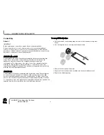
Mains plug replacement
Should your mains plug need replacing and you are competent to do this proceed as
follows. If you are in doubt contact your Linn retailer or a competent electrician.
a) Disconnect the plug from the mains supply.
b) Cut off the plug and dispose of it safely. A plug with bared conductors is
dangerous if engaged in a live socket.
c) Only fit a 13 Amp BS1363A approved plug with a 5 Amp fuse.
d) The cable wire colours or a letter will be marked at the connection points of most
quality plugs.
Attach the wires securely to their respective points. The Brown wire must go to the Live
pin, the Blue wire must go to the Neutral pin, and the Green/Yellow wire must go to the
Earth pin.
e)
Before replacing the plug top ensure that the cable restraint is holding the outer
sheath of the cable firmly and that the wires are correctly connected.
WARNING
THIS APPLIANCE MUST BE EARTHED.
CE Declaration of Conformity
Linn Products Ltd declare that this product is in conformance with the Low Voltage Directive 73/23/EEC and
Electromagnetic Compatibility 89/336/EEC as amended by 92/31/EEC and 93/68/EEC.
The conformity of the designated product with the provisions of Directive number 73/23/EEC (LVD) is proved by
full compliance with the following standards:
S
Stta
an
nd
da
arrd
d n
nu
um
mb
be
err
D
Da
atte
e o
off iis
ss
su
ue
e
T
Te
es
stt tty
yp
pe
e
EN60065 2002
General
requirements
Marking
Hazardous radiation
Heating under normal conditions
Shock hazards under normal
operating conditions
Insulation requirements
Fault conditions
Mechanical strength
Parts connected to the mains supply
Components
Terminal devices
External flexible cords
Electrical connections and mechanical fixings
Protection against electric shock
Stability and mechanical hazards
Resistance to fire
The conformity of the designated product with the provisions of Directive number 89/336/EEC (EMC) is proved by
full compliance with the following standards:
S
Stta
an
nd
da
arrd
d n
nu
um
mb
be
err
D
Da
atte
e o
off iis
ss
su
ue
e
T
Te
es
stt tty
yp
pe
e
EN55013 2001
Conducted
emissions
EN55013 2001
Absorbed
emissions
EN55020 2002
Immunity
FCC notice
NOTE:
This equipment has been tested and found to comply with the limits for a Class B digital device, pursuant to Part
15 of the FCC Rules. These limits are designed to provide reasonable protection against harmful interference in a
residential installation. This equipment generates, uses and can radiate radio frequency energy and, if not
installed and used in accordance with the instructions, may cause harmful interference to radio communications.
However, there is no guarantee that interference will not occur in a particular installation.
If this equipment does cause harmful interference to radio or television reception, which can be determined by
turning the equipment off and on, the user is encouraged to try to correct the interference by one or more of the
following measures:
●
Reorient or relocate the receiving antenna.
●
Increase the separation between the equipment and receiver.
●
Connect the equipment into an outlet on a circuit different from that to which the receiver is connected.
●
Consult the dealer or an experienced radio/TV technician for help.
ii
Important Safety Information
English
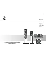
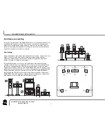
AKURATE Loudspeaker System
Owner’s Manual


