


11
AKURATE Loudspeaker System
Owner’s Manual
AKURATE 221
English
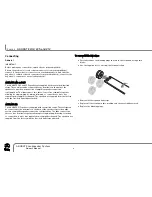
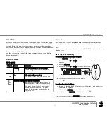
Parameters
The AKURATE 221 speaker is equipped with seven adjustable parameters (see
next page) that enable you to alter its performance to suit your taste.
Note:
The parameters can only be adjusted when the AKURATE 221 speaker is not in
standby mode.
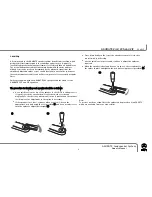
Adjusting the parameters
T
To
o s
se
elle
ec
ctt tth
he
e p
pa
arra
am
me
ette
err y
yo
ou
u w
wiis
sh
h tto
o a
ad
djju
us
stt::
●
Hold F
FE
EA
AT
TU
UR
RE
E.
●
Repeatedly press U
UP
P or D
DO
OW
WN
N until the letter for the desired parameter
appears.
●
Release F
FE
EA
AT
TU
UR
RE
E.
●
Repeatedly press U
UP
P or D
DO
OW
WN
N to change the setting.
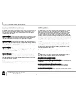
A few seconds after the last key press the display
changes to
T
To
o rre
es
stto
orre
e tth
he
e d
de
effa
au
ulltt s
se
ettttiin
ng
gs
s::
●
Disconnect the AKURATE 221 speaker from the mains supply and wait for
the display to go blank.
●
While holding F
FE
EA
AT
TU
UR
RE
E reconnect the mains supply.
●
Continue to hold F
FE
EA
AT
TU
UR
RE
E until the display shows
H
A few seconds after releasing F
FE
EA
AT
TU
UR
RE
E the display changes to
HP OUT
AL OUT
A IN
-
-
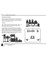
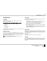
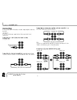
Operation
When you have made all the required connections, switch on the mains supply.
Flashing bars will be shown on the back panel display for approximately 30
seconds. During this time the speaker’s servo circuitry is stabilising and no
audio will be issued. When the display changes to show the standby symbol (see
table below), the speaker is ready to receive an audio signal.
Whenever the AKURATE 221 speaker is disconnected from the mains supply
and then reconnected, wait until the standby symbol appears on the display
before playing a disc.
Operating modes
S
SY
YM
MB
BO
OL
L
M
MO
OD
DE
E
M
ME
EA
AN
NIIN
NG
G
S
Stta
an
nd
db
by
y
T
Th
he
e u
un
niitt iis
s w
wa
aiittiin
ng
g ffo
orr a
an
n a
au
ud
diio
o s
siig
gn
na
all
In this mode the unit consumes minimal
power.
O
On
n
T
Th
he
e u
un
niitt iis
s ffu
ulllly
y p
po
ow
we
erre
ed
d--u
up
p
The unit will enter this mode as soon as it
receives an audio signal.
T
Th
he
errm
ma
all S
Stta
an
nd
db
by
y T
Th
he
e u
un
niitt h
ha
as
s o
ov
ve
errh
he
ea
atte
ed
d
During very demanding, sustained use the
unit will go into Thermal Standby mode in
order to allow itself to cool down. When in
this mode the unit will not produce any
sound. The unit will return to On mode
when its temperature has dropped to its
operating level.
K
Ke
ey
y tto
o s
sy
ym
mb
bo
olls
s


