EtherFast
®
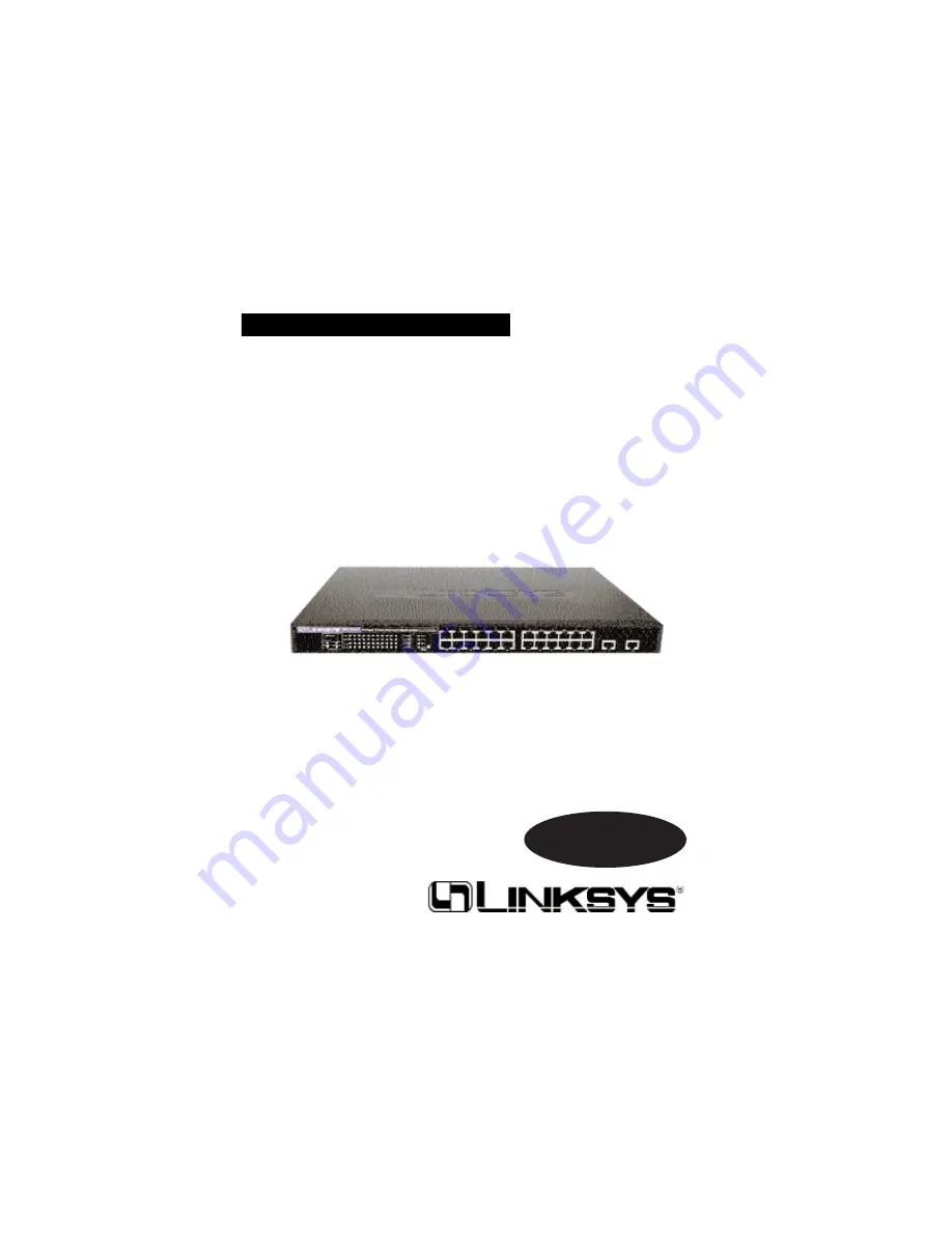
Managed 24-Port
with Dual Gigabit Switch
Use this guide to install:Linksys EtherFast
with Dual Gigabit Switch (EF24G2M)
User Guide
Instant EtherFast
Series
Page 1: ...EtherFast Managed 24 Port with Dual Gigabit Switch Use this guide to install Linksys EtherFast Managed 24 Port with Dual Gigabit Switch EF24G2M User Guide Instant EtherFast Series ...
Page 2: ... Linksys makes no warranty or representation expressed implied or statutory with respect to its products or the contents or use of this documentation and all accompa nying software and specifically disclaims its quality performance merchantability or fitness for any particular purpose Linksys reserves the right to revise or update its products software or documentation without obligation to notify...
Page 3: ...ast Managed 24 Port with Dual Gigabit Switch Perfect for today s network computing demands this new Managed 24 Port Switch from Linksys delivers Layer 3 switching and blazing transfer speeds for your network applications with integrated Gigabit over cop per connectivity The Managed 24 Port Switch s intelligent Layer 3 switching and design provide maximum network control regulating traffic and elim...
Page 4: ... managed via SNMP Console Green The LED will illuminate when the switch is being managed via the local console Fan Failure Green The LED will illuminate when a fan has failed OverHeat Green The LED will illuminate when the switch is overheating PER PORT LNK Green The LED will illuminate when the port is connected Mode Green The LED will illuminate when the port is operating in full duplex mode GIG...
Page 5: ... high speed network segments or individual workstations at speeds of up to 1000Mbps Gigabit Ethernet The two Gigabit ports require UTP Category 5e cable or better The EtherFast Managed 24 Port with Dual Gigabit Switch is equipped with a serial port located on the rear of the switch that allows you to connect to a computer for configuration purposes using the provided serial cable The RJ 45 Ports T...
Page 6: ... to other switches or hubs using a standard Ethernet connection UTP Category 5e or better cable is recommended when using the Gigabit ports To uplink the switch connect one end of a network cable into the Switch then connect the other end of the cable into the desired network device s uplink port 7 EtherFast Series Installing the Switch Fast Ethernet Considerations If you will be using the Switch ...
Page 7: ...n perform various switch configuration and management activities including Enable disable any port Set the communication mode for any port Configure SNMP parameters Add ports to network VLANs Local Console Management You can manage the Switch locally by connecting the switch to a PC or work station with terminal emulation software using the serial port The serial port settings need to be configure...
Page 8: ...tch s configuration program only provides access to basic configuration functions To access the full range of SNMP management functions you must use SNMP based network management software 4 When the following screen appears make sure that the Switch s serial port settings are as follows BAUD RATE 19200 DATA BITS 8 PARITY None STOP BITS 1 FLOW CONTROL None Click the OK button Web Management Web man...
Page 9: ...to the screen for that management setting Highlighting any option selects it pressing the Enter key takes you to that screen To navigate through the Console Interface use the Tab or arrow keys to move the Enter key to select and the Esc key to return to the previous selec tion Scroll through choices using the spacebar Options for the currently selected item are displayed in the highlighted area at...
Page 10: ...atus and Gigabit port usage of the Switch Select OK to return to the previous panel 14 System Information The System Information screen displays descriptive information about the Switch or system System Description System hardware description System Object ID MIB II object identifier for the Switch s network management subsystem System Up Time Length of time the current management agent has been r...
Page 11: ...s User Configuration Sets the user names and passwords for system access TFTP Download Downloads new version of firmware to update your system Configuration File Allows downloading of a configuration file Select OK to return to the previous panel Management Setup Menu Switch Information The Switch Information screen displays hardware and firmware version num bers for the main board as well as the ...
Page 12: ... management station is located in a different IP segment IP State Specifics whether IP functionality is enabled via manual con figuration default setting or set by Boot Protocol BOOTP Select Apply to make changes Select OK to return to the previous panel Select Cancel to cancel any changes 18 Network Configuration The Network Configuration menu allows you to set the Switch s IP address configure t...
Page 13: ...any changes 21 IP Connectivity Test Ping The IP Connectivity Test is used to see if another site or node on the net work can be reached IP Address IP address of the device you want to ping Test Times The number of ICMP echo requests to send to the specified site Range varies from 1 to 1000 Success Failure The number of times the specified site has responded or not to a ping request Note There is a...
Page 14: ...ort Baud Rate The rate at which data is sent between devices Default is 19200 Options are 9600 19200 and 38400 baud Data Bits Sets the data bits of the RS 232 port Options are 7 and 8 Stop Bits Sets the stop bits of the RS 232 port Options are 1 and 2 Parity Sets the parity of the RS 232 port Default is None Options are none odd and even Time Out If no input is received from the attached device af...
Page 15: ...changes Select OK to return to the previous panel Select Cancel to cancel any changes 25 SNMP Communities The SNMP Communities screen allows you to configure the community strings authorized for management access Up to five community names may be entered Community Name A community entry authorized for management access Maximum string length is 19 characters Access Management access is restricted t...
Page 16: ...rm the changes Select Cancel to cancel any changes 27 EtherFast Series User Configuration The User Configuration screen to restrict management access based on speci fied user names and passwords There are two user types Administrator and Guest Only the Administrator has write access for parameters governing the SNMP agent User Name Specifies user authorized management access to the Switch via the ...
Page 17: ... PC Upload to switch Uploads a configuration file to the Switch from the client PC Select Start to begin the download Select Cancel to cancel the download 29 EtherFast Series TFTP Download The TFTP Download screen lets you load software updates to permanent flash ROM in the Switch After downloading the new software the agent will automatically restart itself Download Server IP IP address of a TFTP...
Page 18: ... shots shows the Device Control Menu displayed by a mul tilayer switch System Mode Sets the Switch to operate as a Layer 2 switch or as a mul tilayer routing switch Layer 2 Menu Configures port communication mode mirror ports and port trunking Bridge Menu Configures the Spanning Tree Protocol for the bridge or for specific ports GMRP and GVRP for automatic registration of multi cast and VLAN group...
Page 19: ...lly configure host MAC addresses in the multicast table Select OK to return to the previous panel 33 EtherFast Series System Mode The System Mode screen lets you set the Switch to operate as a Layer 2 switch or as a multilayer routing switch As a Layer 2 switch the Switch makes all filtering and forwarding decisions based strictly on MAC address es As a multilayer routing switch it switches packet...
Page 20: ...e source port Enable Port Mirror Enables or disables the mirror function Mirrored Ports Tx Rx The port whose transmitted or received traffic will be mirrored Press Add to specify mirrored ports 35 EtherFast Series Port Configuration The Port Configuration screen lets you display or set communication parameters for any port or module on the Switch including administrative status auto negotiation de...
Page 21: ...ss Apply 37 EtherFast Series Monitor Port The port that will duplicate the transmitted or received traffic appearing on the mirrored port Note You can mirror multiple ports to a single port to view traffic such as that crossing a port trunk However note that some packets may be dropped for moderate to heavy loading Select Apply to make changes Select OK to return to the previous panel Select Add t...
Page 22: ... 26 For each port number there are two choices If the letter M is present it indicates that the VLAN has access to messages transmitted by that particular port If there is no letter M then there is no access to messages trans mitted by that particular port Select Apply to make changes Select OK to return to the previous panel Select Prev Page to view the previous page Select Next Page to view the ...
Page 23: ...ty path cost and fast forwarding Select OK to return to the previous panel 41 EtherFast Series Add Multicast Address Entry The Add Static Address Entry screen allows you to add static addresses for multicasting VLAN The VLAN corresponding to this multicast service Address The destination MAC address for a multicast service Port The ports to which this multicast traffic can be forwarded Read the nu...
Page 24: ...cost for all ports on a switch are the same the port with the highest priority that is lowest value will be configured as an active link in the Spanning Tree When more than one port is assigned the highest 43 EtherFast Series Bridge Configuration The Bridge Configuration screen allows you to configure global bridge settings Spanning Tree Enable this parameter to participate in a STA compliant netw...
Page 25: ...ast traffic to the originating group This also provides a more secure and cleaner network environment VLAN Port Configuration Configure GARP the default VLAN identi fier default port priority VLAN tagging on the attached link GVRP and 44 GMRP status and filtering of incoming frames for VLAN groups a spe cific port does not belong to VLAN Table Configuration Use this screen to create a new VLAN or ...
Page 26: ... traffic generated by nodes rejoining the group VLAN and Priority These fields set the default values for VLANs port priority GVRP and GMRP Port VID The VLAN ID assigned to untagged frames received on this port Port Default Priority Sets the default ingress priority to any value beneath the priority threshold to specify the low priority queue or to any value equal to or above this threshold to spe...
Page 27: ... Routing Protocol Select Apply to make changes Select OK to return to the previous panel Select Cancel to cancel any changes Select Prev Page to view the previous page Select Next Page to view the next page To display a specific page set the page number in the Page field and then press Apply Select Add to add an IP interface 49 EtherFast Series IP Menu The IP Menu is used to configure the IP subne...
Page 28: ...dd tional configuration See page 64 DVMRP Distance Vector Multicast Routing Protocol Select Apply to make changes Select OK to return to the previous panel Select Cancel to cancel any changes 51 EtherFast Series Add Subnet The Add Subnet screen allows you to add an IP interface VLAN The VLAN associated with this IP interface Select Use this option to create or modify a VLAN IP Address The IP addre...
Page 29: ...ages Static Route Advertisement Static route messages Ignore Host Route Does not use host routes Select Apply to make changes Select OK to return to the previous panel Select Cancel to cancel any changes 53 EtherFast Series ARP Configuration The ARP Configuration screen allows you to specify the timeout duration ARP Timeout Duration of timeout in minutes Select Apply to make changes Select OK to r...
Page 30: ... view the next page To display a specific page set the page number in the Page field and then press Apply Select Add to add a static ARP entry 55 EtherFast Series BOOTP Relay Database Configuration The BOOTP Relay Database Configuration screen allows you to specify the IP address for a BOOTP relay server Index Server Address Used to define any preferred DHCP servers or the outbound subnetwork for ...
Page 31: ...ch IP address on a specific IP subnetwork Bcast A subnetwork broadcast address Mcast An IP multicast address Invalid An illegal IP address to be filtered Select Apply to make changes Select OK to return to the previous panel Select Prev Page to view the previous page Select Next Page to view the next page To display a specific page set the page number in the Page field and then press Apply Select ...
Page 32: ...ed to reach the default router Select Delete to delete the route Select OK to return to the previous panel Select Cancel to cancel any changes 59 EtherFast Series Add Routing Entry The Add Routing Entry screen is used to add a routing entry IP Address IP address of static ARP entry MAC Address MAC address of static ARP entry Interface Identification number for interface of static ARP entry Routing...
Page 33: ...s panel Select Prev Page to view the previous page Select Next Page to view the next page To display a specific page set the page number in the Page field and then press Apply 61 EtherFast Series Security Menu The Security Menu is used to configure security options MAC Filtering Configuration Security filtering can be used to drop all the traffic from a host device based on a specified MAC address...
Page 34: ...ct Cancel to cancel any change 62 IP Security Filtering Configuration Security filtering can be used to drop all the traffic from a specified IP address Only available when the Switch is in multilayer mode To add an IP address use Add To delete an address highlight it with the cur sor and press Enter Select Apply to make changes Select OK to return to the previous panel Select Prev Page to view th...
Page 35: ...warding VLAN traf fic in the VLAN Forwarding Information table 65 EtherFast Series IGMP Snooping Configuration The IGMP Snooping Configuration allows you to set up IGMP snooping IGMP snooping is used to monitor for any attached hosts who want to receive a specific multicast service It looks up the IP Multicast Group used for this service and adds any port that received a similar request to that gr...
Page 36: ...r layer protocol One possible reason for discarding such a packet could be to free up buffer space 67 IP Multicast Registration Table Displays all the multicast groups active on this Switch including the multicast IP address and the corresponding VLANs Only displayed for Layer 2 mode When the Switch is in multi layer mode IP Multicast Registration Table is available through the IP Menu IP Menu Dis...
Page 37: ...n Errors The number of inbound packets that contained errors pre venting them from being deliverable to a higher layer protocol Alignment Errors The number of alignment errors mis synchronized data packets Out Octets The total number of octets transmitted out of the interface including framing characters Out Unicast Pkts The total number of packets that higher level proto cols requested be transmi...
Page 38: ...uding FCS octets 128 255 Byte Frames The total number of frames including bad pac ets received and transmitted where the number of octets fall within the specified range excluding framing bits but including FCS octets 256 511 Byte Frames The total number of frames including bad pack ets received and transmitted where the number of octets fall within the specified range excluding framing bits but i...
Page 39: ...he total number of frames including bad packets received and transmitted where the number of octets fall within the specified range excluding framing bits but including FCS octets Select Apply to make changes Select Refresh to refresh the statistics Select OK to return to the previous panel Select Reset to reset a specific statistic Select Reset All to reset the all statistics Select Prev Port to ...
Page 40: ...panning Tree Bridge Information The STA Bridge Information screen displays a summary of STA informa tion for the overall bridge Priority Device priority is used in selecting the root device root port and designated port The device with the highest priority becomes the STA root device However if all devices have the same priority the device with the lowest MAC address will then become the root devi...
Page 41: ...forward packets Listening Port will leave blocking state due to a topology change starts transmitting configuration messages but does not yet forward packets Learning Port has transmitted configuration messages for an interval set by the Forward Delay parameter with out receiving contradictory information Port address is cleared and the port begins learning addresses Forwarding The port forwards p...
Page 42: ...lect Next Page to view the next page To display a specific page set the page number in the Page field and then press Apply 79 EtherFast Series VLAN Dynamic Registration Information The VLAN Dynamic Registration Information screen shows the ports that have been automatically learned via GVRP VLAN The ID for the VLAN Port The ports on the Switch Read the numbers vertically they range from 1 26 For e...
Page 43: ...See page 80 Select OK to return to the previous panel 81 EtherFast Series IP Multicast Registration Table The IP Multicast Registration Table displays all the multicast groups active on the Switch including the multicast IP address and the corresponding VLANs VLAN A VLAN with host members that have asked to receive the indi cated multicast service Multicast IP A source IP address that represents a...
Page 44: ...ce for VLANs configured on this Switch IP Address The IP address associated with the specified VLAN inter face Subnet Mask A template that identifies the address bits in the host address used for routing to specific subnets VLAN The VLAN associated with this IP interface Ports The ports on the Switch Read the numbers vertically they range from 1 26 For each port number there are two choices S or P...
Page 45: ...lticast groups active on the Switch including the multicast IP address and the corresponding VLANs See page 80 IGMP Cache Cache for IGMP 85 EtherFast Series Routing Table The Routing Table lists the routes through which all recognized Ethernet networks and corresponding VLAN can be reached Destination Network A destination network subnet or host Destination Mask The subnet mask that specifies the ...
Page 46: ...Select Next Page to view the next page To display a specific page set the page number in the Page field and then press Apply 87 EtherFast Series Multicast Forwarding Cache Table Cache for multicast forwarding DVMRP Routing Table Routing table for Distance Vector Multicast Routing Protocol DVMRP Neighbor Table Table of neighbors for Distance Vector Multicast Routing Protocol Select OK to return to ...
Page 47: ...ct Next Page to view the next page To display a specific page set the page number in the Page field and then press Apply 89 EtherFast Series Multicast Forwarding Cache The Multicast Forwarding Cache displays the settings for the cache Group Address An IP multicast group address with subscribers directly attached or downstream from this Switch Source Address The IP subnetwork at the root of the mul...
Page 48: ...at connects to the upstream neighbor Neighbor Address The IP address of the network device immediately upstream for this multicast delivery tree UpTime The time since this device last became a DVMRP neigh bor to this Switch ExpireTime The time remaining before this entry will be aged out Ver The neighboring router s DVMRP version number RcvRoute The total number of routes received in valid DVMRP p...
Page 49: ... address subnet mask and default gateway Layer 2 Check that you have a valid network connection to the Switch and that the port you are using has not been disabled Check the network cabling between the management station and the Switch If you cannot connect using telnet there may already be four active sessions Try connecting again at a later time 2 I forgot or lost the password Reinstall the swit...
Page 50: ...rogram via a serial port configura tion Be sure you have set the terminal emulator program to VT100 compati ble 8 data bits 1 stop bit no parity and 19200 bps Check that the null modem serial cable conforms to the pin out con nections provided below DB 9 Port Pin Assignments Console Port to 9 Pin COM Port on PC Console Port to 25 Pin DCE Port on Modem 94 ...
Page 51: ... screen appears as shown below press D to download system firmware and then indicate the code type r Runtime image or d Diagnostic image 96 Upgrading Firmware via the Serial Port POST Version V2 55 A03 8 18 2000 Power On SElf Test POST Int Loopback Testing SCC2 UART Channel PASS Testing the System SDRAM PASS Int Loopback Testing _____UART Channel PASS Int Loopback Testing _____UART Channel PASS CP...
Page 52: ...s when a computer is plugged into a different place in the network DHCP uses the concept of a lease or amount of time that a given IP address will be valid for a computer The lease time can vary depending on how long a user is likely to require the Internet connection at a particular location It s especially useful in education and other environments where users change fre quently Using very short...
Page 53: ...1 EtherFast Series 100 DVMRP Distance Vector Multicast Routing Protocol Used for routing multi cast messages through the Internet Dynamic Routing The ability for a router to forward data via a different route based on the current conditions of the communications circuits For example it can adjust for overloaded traffic or failing lines and is much more flexible than static routing which uses a fix...
Page 54: ... Series Network A system that transmits any combination of voice video and or data between users NIC Network Interface Card A board installed in a computer system usu ally a PC to provide network communication capabilities to and from that com puter system Also called an adapter Port A pathway into and out of the computer or a network device such as a switch or router For example the serial and pa...
Page 55: ...OR SHIPPING AND HANDLING CHARGES PLEASE CALL LINKSYS FOR MORE DETAILS Specifications Model Number EF24G2M Standards IEEE 802 1D IEEE 802 1p IEEE 802 1Q IEEE 802 3 IEEE 802 3ab IEEE 802 3u IEEE 802 3x Protocol CSMA CD Ports 24 10 100Base TX RJ 45 Ports 2 1000Base T RJ 45 Ports 1 RS 232 DB 9 Port Speed Per Port Mbps 10 100 Ports 10 or 100 Half Duplex 20 or 200 Full Duplex 1000 Ports 1000 Half Duplex...
Page 56: ...of this product contact Linksys Customer Support at one of the phone numbers or Internet addresses below Sales Information 800 546 5797 LINKSYS Tech Support 888 793 5932 RMA Issues 949 261 1288 Fax 949 261 8868 Email support linksys com Web http www linksys com FTP Site ftp linksys com ...
Page 57: ... Copyright 2001 Linksys All Rights Reserved Printed in the USA http www linksys com ...