Link4 iPonic 614 Installation And User Manual Download Page 18

 
960-3100-00 

    iPonic 614 Installation Manual 

12  


Alarms 

 
Alarm Function 

The  iPonic

TM

  614  will not only control your hydroponic environment but it will also notify you if the 

conditions of your growing environment become unacceptable. You can determine which temperature, 
humidity and CO

2

 conditions may require human intervention and for you to be notified. When an alarm 

condition exists the alarm will display above the temperature reading on the main status screen of the 
controller. You can also  setup additional notification methods such as text or email alerts through the 
iPonic Cloud or an alarm output such as a Sensaphone Alarm Dialer. 
 
There are alarm conditions preprogrammed into your iPonic

TM

  614  controller.  By default, the alarm 

condition must exist for a full minute before the controller will issue an alarm. After another full minute of a 
high temperature alarm, the controller  will power off an installed light bank in an attempt to cool the 
hydroponic environment. 


High Alarm 

Low Alarm 

                                Temperature 

100ºF (38.7ºC) 

50ºF (10.0ºC) 

                               Humidity 

90%RH 

20%RH 

                               CO

2


2000ppm 

600ppm 


Alarm Delay 

Light Off Delay 

60 seconds


60 seconds to Temp (L2) 


Figure 1.2 Alarm Default Settings 


Changing the Alarm Settings 

From the home screen of your iPonic

TM

 614, press the menu button. Select option 3, “System Setup” with 

the wheel and press OK. Select option 4, “Alarms Setup” with the wheel and press OK. The screen will 
display your current alarm settings. Press the UI button corresponding with the alarm threshold you would 
like to change. Use the wheel to adjust the threshold value by an increment of 0.1º for temperature, 1% 
for humidity or 1ppm for CO

2

 or you can press button 1 to change this to another increment and then use 

the wheel to change the threshold value. When you are done making your changes, press OK. Press OK 
again to confirm and save your changes. 
 

Receiving Alarm Notifications by Text or Email through the Cloud (Recommended) 

If you would like your alarm notifications delivered via text or email, you will first need to have the optional 
Communications Module installed and connected to the internet (see previous chapter and section, 

Connecting to the Internet.

)  When connecting to the internet you will have created an account at 

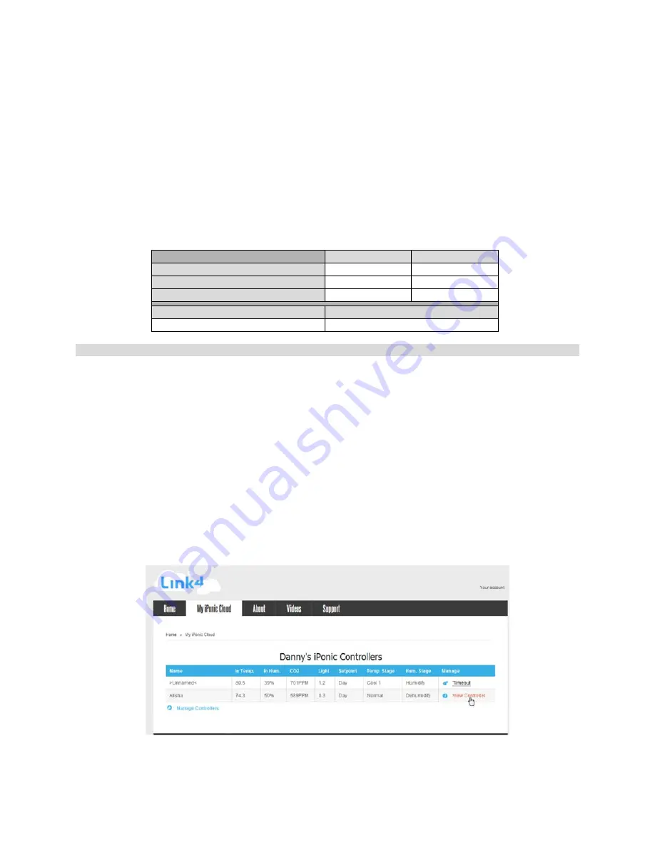
http://www.iponic.link4cloud.com, to enable alarm notifications login to your account.  
 
You can open your controller settings by clicking “View Controller.” 


Summary of Contents for iPonic 614

Page 1: ...iPonic 614 INTELLIGENT ENVIRONMENTAL CONTROLLER Installation and User s Guide October 2012 Edition Copyright 2012 Corporation...

Page 2: ...960 3100 00 iPonic 614 Installation Manual II...

Page 3: ...Changing Light Settings 9 CO2 Control 9 CO2 Injector Setup 9 Changing CO2 Target Settings 9 Temperature Control 9 Heater Setup 9 Ventilation Fans Setup 10 Air Conditioner Setup 10 Central Heating and...

Page 4: ...ht Timer 23 Separate Light Bank Enable 23 Power Cool Down Time 24 Advanced Temperature Controls 24 Temperature Stages 24 Programming Additional Temperature Stages 24 Stage Separation Width 25 Changing...

Page 5: ...tput 31 Wiring a Sensaphone to Dry Contacts 31 Administrative Settings 33 View Model Number and Firmware Versions 33 Upgrade Restore Controller Firmware 33 Password Protect Controller 33 To Save Resto...

Page 6: ......

Page 7: ...reason why we stand out from others is because of our Link4 Promise Our passion is to provide growers with intelligent control solutions We understand controlling your growing environment is critical...

Page 8: ...reserves the right to make any necessary changes to features and specifications to condition or warranty Support In order to offer you the best support we request that you register your product with...

Page 9: ...the iPonicTM 614 controller The area should be away from direct sunlight condensation humidity rain and extreme temperatures It should be mounted in an easily accessible location at the user s eye le...

Page 10: ...from Link4 If any splices are needed to extend cable length make certain they are WATERTIGHT Water or fertilizer infiltration WILL cause unstable sensor readings 4 Keep sensor cables away from interfe...

Page 11: ...e main status screen Press the menu button Press 3 for System Setup then OK Press 8 for Communication Setup then OK Press 2 for Server Setup then OK You can now view your serial number and registratio...

Page 12: ...960 3100 00 iPonic 614 Installation Manual 6 Equipment Setup Main Status Screen...

Page 13: ...by pressing OK A table will appear showing the available equipment types From this table you can select up to 6 outputs The default equipment types are lights output 1 outlet 1 CO2 injector output 2...

Page 14: ...vironment back to the normal range for that time setpoint A humidify and dehumidify setpoint can be set for each of your time setpoints which will activate installed equipment when the humidity falls...

Page 15: ...e selected the correct time Press OK again to save your changes To adjust the end time of your Day time setpoint the beginning of your Night time setpoint press button 6 from the Light Setting screen...

Page 16: ...ll be turned off Whenever the temperature within your hydroponic facility moves above the cool setpoint or below the heat setpoint falls outside the Normal temperature range the iPonicTM 614 can enter...

Page 17: ...tpoint Use the wheel to adjust the humidity setpoint by an increment of 1 or you can press button 1 to change this increment to 10 and then use the wheel to change the humidity setpoint Press OK Press...

Page 18: ...y Light Off Delay 60 seconds 60 seconds to Temp L2 Figure 1 2 Alarm Default Settings Changing the Alarm Settings From the home screen of your iPonicTM 614 press the menu button Select option 3 System...

Page 19: ...Internet and deliver them to their customers cell phones as SMS text messages Every provider assigns a unique domain for their customers address so check with your provider to identify your cell phon...

Page 20: ...2 3 Set Dehumidify Setpoint 1 2 4 Global Humidity Settings 1 2 4 1 Set On Time Minutes 1 2 4 2 Set On Time Seconds 1 2 4 3 Set Off Time Minutes 1 2 4 4 Set Off Time Seconds 1 2 4 5 Deadband 1 3 CO2 S...

Page 21: ...2 2 Graphs 2 2 1 Temperature 2 2 1 1 Inside Temperature 2 2 1 1 1 Since Reset 2 2 1 1 2 Last Hour 2 2 1 1 3 Last 24 Hours 2 2 1 1 4 Last 7 days 2 2 1 2 Heat Setpoint Same suboptions as Inside Temperat...

Page 22: ...8 Set up to one timed override for each output 3 1 2 1 Light 3 1 2 1 1 Timed Override 3 1 2 1 1 1 Enable Disable Override 3 1 2 1 1 2 Override to On Off 3 1 2 1 1 3 Start Time 3 1 2 1 1 4 Duration 3 1...

Page 23: ...et Name 3 1 2 4 DeHum 3 1 2 4 1 Timed Override 3 1 2 4 1 1 Enable Disable Override 3 1 2 4 1 2 Override to On Off 3 1 2 4 1 3 Start Time 3 1 2 4 1 4 Duration 3 1 2 4 1 5 Daily One time 3 1 2 4 2 Type...

Page 24: ...nable or disable sensors 3 3 2 Advanced 3 3 2 1 Map Sensors 3 3 2 2 Calibrate Sensors 3 4 Alarms Setup 3 4 1 HighTemp Alarm Threshold 3 4 2 HighHum Alarm Threshold 3 4 3 HighCO2 Alarm Threshold 3 4 4...

Page 25: ...ange 3 6 5 1 Air Dump on off 3 6 6 Adv Stage Settings 3 6 6 1 Stage Show Hide 3 6 6 2 Stage Delay 3 6 6 3 Heat Stages 3 6 6 4 Cool Stages 3 6 7 Adv Setpoint Settings 3 6 7 1 CO2 Night Setpoint 3 6 7 2...

Page 26: ...Save Restore Config 3 7 1 1 Save Configuration 3 7 1 2 Restore Configuration 3 7 1 3 Delete Configuration 3 7 2 Save Log Files 3 7 2 1 Save History Log Files 3 7 2 2 Save Event Log Files 3 7 2 3 USB L...

Page 27: ...614 Installation Manual 21 3 8 2 1 Set to Private Server 3 8 2 2 Reset Regist Key 3 9 Measurement Units 3 9 1 Temp Units 3 9 2 Light Units 4 Save Restor Config 4 1 Save Schedule 4 2 Restore Schedule 4...

Page 28: ...s the unit itself seen in figure 1 1 in the previous section The flowering phase and the weeks that fall within it have a shorter day setpoint lasting from 5 00AM to 5 00PM and the cool setpoint for t...

Page 29: ...e you choose One programmed override per piece of equipment is allowed Menu SystemSetup 1 Equipment Setup 2 Advanced Choose Equipment button 1 Timed Override button 1 to Enable Disable Menu SystemSetu...

Page 30: ...ooling will be brought to attempt to bring the air temperature below the cool setpoint and within the target Normal temperature range Heating works the same way as the temperature of your facility fal...

Page 31: ...ed button 2 for Global Temp Settings button 2 for Stage Width wheel Deadbands While cooling or heating equipment may be engaged as soon as the measured temperature falls outside of the normal range a...

Page 32: ...Control Switching between Tank and Generator When you initially chose a CO2 output in Equipment Setup you were prompted to choose a CO2 equipment type of either CO2 Generator or CO2 Tank To view or c...

Page 33: ...d press 1 to change increment OK Fuzzy Logic Employing Fuzzy Logic with your controller s advanced settings will allow your CO2 target to be met based on the amount of need rather than treating every...

Page 34: ...ure Control section The three humidity stages are humidify dehumidify and cold dehumidify For each humidity stage you will need to choose whether to override your temperature stage settings and force...

Page 35: ...o the motor However in some cases such as and alarm unit or irrigation valves that are 24 VAC you can drive them directly assuming that you are wiring only one or two valves per relay The maximum curr...

Page 36: ...you will program this as a fan Finally connect the white wire from your AC Heater to the 5 relay you will program this as your heater To program this setup First you will want to give each output the...

Page 37: ...arm output is not one of the basic equipment types but can easily be added to your controller An advanced setting will allow you to choose any of the 8 outputs including the unnamed relays and set the...

Page 38: ...res as shown in Figure 9 Make sure you test the Sensaphone by programming a high and low limit if both relays are used either if one relay is used and then make the alarms go off to see if the Sensaph...

Page 39: ...Defaults Change Date Time Menu SystemSetup 5 Time Date Setup button 1 to set time button 2 to set date Rerun Startup Wizard Will prompt you to enter the date and time equipment types and the CO2 equi...

Page 40: ...store 2 Save Log Files button 1 to save history log file button 2 to save event log files button 3 to enable and setup USB logging Diagnostics Menu SystemSetup 6 Advanced More button 7 for Diagnostics...

Page 41: ...ty Setpoint 1 2 1 Switch Period 1 2 2 Set Humidify Setpoint 1 2 3 Set Dehumidify Setpoint 1 2 4 Global Humidity Settings 1 2 4 1 Set On Time Minutes 1 2 4 2 Set On Time Seconds 1 2 4 3 Set Off Time Mi...

Page 42: ...zzy 1 3 3 7 2 Edit 1 4 Light Setting 1 4 1 Change Light Banks Mode Option appears if more than one light output is setup 1 4 2 Start Time 1 4 3 End Time 1 4 4 Light Timing Method Option appears if you...

Page 43: ...rent Setpoints 2 3 Setpoint By Week 2 3 1 GrowWeek 01 04 2 3 1 1 GrowWeek 01 Same suboptions as Current Setpoints 2 4 Duration Settings 2 4 1 Disable Enable Growth Curve 2 4 2 Total Duration 2 4 3 Veg...

Page 44: ...midity Same suboptions as Inside Temperature 3 2 2 2 Humidify Setpoint Same suboptions as Inside Temperature 3 2 2 3 Dehumidify Setpoint Same suboptions as Inside Temperature 3 2 3 Light Same suboptio...

Page 45: ...as Output 1 Name 4 1 2 3 Output 3 Name Same suboptions as Output 1 Name 4 1 2 4 Output 4 Name Same suboptions as Output 1 Name 4 1 2 5 Output 5 Name Same suboptions as Output 1 Name 4 1 2 6 Output 6...

Page 46: ...m Threshold 4 4 4 Alarm Delay 4 4 5 LowTemp Alarm Threshold 4 4 6 LowHum Alarm Threshold 4 4 7 LowCO2 Alarm Threshold 4 4 8 Light Off Delay 4 5 Time Date Setup 4 5 1 Set Time 4 5 2 Set Date 4 6 Advanc...

Page 47: ...e Delay 4 6 6 3 Heat Stages 4 6 6 4 Cool Stages 4 6 7 Adv Setpoint Settings 4 6 7 1 CO2 Night Setpoint 4 6 7 2 Enable Disable DIF Setpoint 4 6 7 3 Enable Disable Ramping 4 6 7 4 Enable Disable CO2 Fuz...

Page 48: ...CO2 Cut off with light meter 4 7 Save Restore 4 7 1 Save Restore Config 4 7 1 1 Save Configuration 4 7 1 2 Restore Configuration 4 7 1 3 Delete Configuration 4 7 2 Save Log Files 4 7 2 1 Save History...

Page 49: ...Reset Regist Key 4 9 Measurement Units 4 9 1 Temp Units 4 9 2 Light Units 5 Save Restor Config 5 1 Save Schedule 5 2 Restore Schedule 5 3 Delete Schedule 6 Stages This option appears when Stage Show H...

Page 50: ...heet is for irrigation The iPonicTM 614 supports 2 modes of irrigation Please see the Programming Section of this manual for additional information on these modes If there are no plans for irrigation...

Page 51: ...STAGE CO2 MINIMUM LIGHT LEVEL W m2 START TIME hh mm END TIME hh mm MINIMUM CO2 LEVEL ppm MAXIMUM CO2 LEVEL ppm Cycle Trigger Worksheet for Irrigation 1 2 3 4 5 6 7 8 9 10 11 12 START TIME hh mm END TI...

Page 52: ...re Humidity CO2 Week Start On Off 1 2 Heat Setpt Cool setpt Humidify DeHumidify Target 1 RH RH ppm 2 RH RH ppm 3 RH RH ppm 4 RH RH ppm 5 RH RH ppm 6 RH RH ppm 7 RH RH ppm 8 RH RH ppm 9 RH RH ppm 10 RH...

Reviews: