background image

4 – Door Operator / STA / LC- 2973 Rev.H 

5.1 Preparation

Danger! 

To avoid injury, the following points must 
be observed:
-  The operator must be installed free of 

any tension.

-  The operator must not move on the  

shaft.

-  The design and subsurface of all 

components must be suitable for the 
forces encountered.

Warning! 

To avoid damage to the operator and the 

door, the operator must only be fitted if:

-  the operator is undamaged,
-  the ambient temperature is -20 ºC to  

+60 ºC,

-  the altitude of the location does not 

exceed 1,000 m,

-    a suitably rated mains protection device 

has been selected.


Before installation, ensure that: 
- the operator is not blocked,  
- the operator has been newly prepared after a lengthy  

-

 storage period,  

- all connections have been carried out correctly,  
- the direction of rotation of the drive motor is correct,  
- all motor protective devices are active,  
- no other sources of danger exist, 

-  the installation site has been cordoned off over a 

wide area.

Information

The relevant instruction for the door must 

be observed when fitting the drive to the 

door.
-    a suitably rated mains protection device 

must be selected.

5.2  STA Sectional Operator 

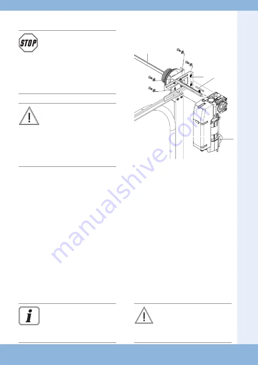
Mounting with torque bracket - example

A

B

C

D


Fit the torque support bracket/console (A).


Grease the spring shaft (B) around the operator 
seating.


Insert the feather key (C) into the spring shaft (B).


Place the operator (D) on the spring shaft (B).


Secure the feather key (C) against any move-
ment.

The feather key can be secured with two hose 
clamps or adjusting rings. 


Fix the operator to the torque support bracket 
with 4 bolts.

Warning! 

Damage due to improper installation the 
drive! To avoid damage to the drive and to 
the door, the drive must be mounted on a 
torque support bracket that it is vibration 
damped.

5.   Installation

Summary of Contents for CDO 100: 1:10-30

Page 1: ...STA LC 2973 Rev H Stuart Road Manor Park Runcorn Cheshire WA7 1TS T 44 0 1928 579050 F 44 0 1928 579259 www linkcontrols co uk enquiries linkcontrols co uk Warning Please read these instructions fully...

Page 2: ...levant regulations trained in the use and care of appropriate safety equipment Capable of recognising the dangers associated with installation Only qualified and trained electricians may connect the o...

Page 3: ...tuations EN 61000 6 2 Electromagnetic compatibility EMC Part 6 2 Generic standards Immunity for industrial environments EN 61000 6 3 Electromagnetic compatibility EMC Part 6 3 Generic standards Emissi...

Page 4: ...of the drive motor is correct all motor protective devices are active no other sources of danger exist the installation site has been cordoned off over a wide area Information The relevant instructio...

Page 5: ...quality of its goods and as such reserves the right to replace modify products without prior notification Any examples given are inteded for guidance only 5 3 CDO100 Compact Operator Flange Mount Han...

Page 6: ...ng in shaft failure Ensure the keysteel is secured in the keyway 2 Ensure the keysteel is secured in the keyway and fit the drive shaft ensuring that the shaft comes flush with hollow shaft on the non...

Page 7: ...e opposite side 1 Remove the plastic caps if fitted from hollow shaft of the operator 2 Ensure the keysteel is secured in the keyway and fit the drive shaft ensuring that the shaft comes flush with ho...

Page 8: ...oading on the shaft resulting in shaft failure 5 5 Installation of the emergency hand chain for operators with emergency hand chain Information To ensure that they work correctly the chain links must...

Page 9: ...al currents and the type of connection must correspond to those on the motor type plate The drive details must agree with the connected loads Information When operated with electronic control units th...

Page 10: ...les Customer Connections D Motor Supply Connections 1 2 3 E Limit Switch Connections 6 Common 7 Open Limit 8 Close Limit 9 Pre Close Limit F Thermal Interlock Connections 4 5 G Cap Switch Option Wirin...

Page 11: ...Setting Mechanical Limits M Fine adjustment screw N Locking screw Each control cam has a locking screw N and a fine adjustment screw M The locking screw N is used to lock the corresponding control cam...

Page 12: ...ating manual for instructions on setting the limit end positions A B Wiring allocation AVE absolute value encoder plug The numbers on the plug are also the wire numbers 4 Safety circuit input N C 5 RS...

Page 13: ...erator is leaking oil If the operator makes unusual noises or leaks oil The operator must be taken out of service immediately Contact technical support Danger To avoid injury the following points must...

Page 14: ...gency hand crank into the operator as far as it will go Move the door in the OPEN or CLOSE direction by turning the emergency hand crank Remove the emergency hand crank from the operator after complet...

Page 15: ...h the operator 8 Maintenance Warning To avoid damage to the operator and door the following points must be observed Maintenance must only be carried out by authorized persons Directive BGR 232 must be...

Page 16: ...to change modify products without prior notification 20 02 2017 9 EC Declaration of Incorparation Authorised Distributor Link Controls Stuart Road Manor Park Runcorn Cheshire WA71TS Door GateOperators...

Reviews: